Hologram element, method for manufacturing the same, and hologram laser and optical pickup

A holographic element and manufacturing method technology, applied in the field of holographic elements, can solve the problems of high manufacturing cost, decreased cutting knife sharpness, shaking, etc.

Inactive Publication Date: 2008-06-11
SHARP KK
View PDF2 Cites 0 Cited by
  • Summary
  • Abstract
  • Description
  • Claims
  • Application Information

AI Technical Summary

Problems solved by technology

Therefore, if the diffracted light of the light incident from the holographic surface can be ensured to pass through the area of ​​the grating surface in the diffraction direction of the light incident from the holographic surface, then the optical performance is sufficient, but the holographic surface and the grating surface are rectangular hologram elements. High manufacturing cost due to large size
However, in the case of manufacturing a holographic element with a holographic surface and a grating surface other than a rectangular shape, after cutting the wafer in one direction, when cutting the second direction, due to the angle of the cutting blade relative to the cutting line in the first direction, The angle is not a right angle, so, due to the force that makes the knife advance, there is wobble in the direction away from this force
In addition, the wafer is attached to the adhesive sheet, and after being subdivided by cutting in the first direction, it does not move completely, but deflects to a certain extent relative to the external force. Therefore, when cutting in the second direction, Cannot cut in desired shape
Especially in the case where the sharpness of the cutting knife decreases due to repeated use of the knife, this disadvantage is significant.
In addition, as in the past, when the hologram element is made of glass, it is difficult to cut because of its hardness, so this disadvantage is notable.
Therefore, in order to ensure the dimensional accuracy of holographic elements, it is difficult to manufacture elements of other shapes than rectangular

Method used


Image

  • Hologram element, method for manufacturing the same, and hologram laser and optical pickup
  • Hologram element, method for manufacturing the same, and hologram laser and optical pickup
  • Hologram element, method for manufacturing the same, and hologram laser and optical pickup

Examples


Embodiment Construction

[0080] Preferred embodiments of the present invention will be described in detail below with reference to the accompanying drawings.

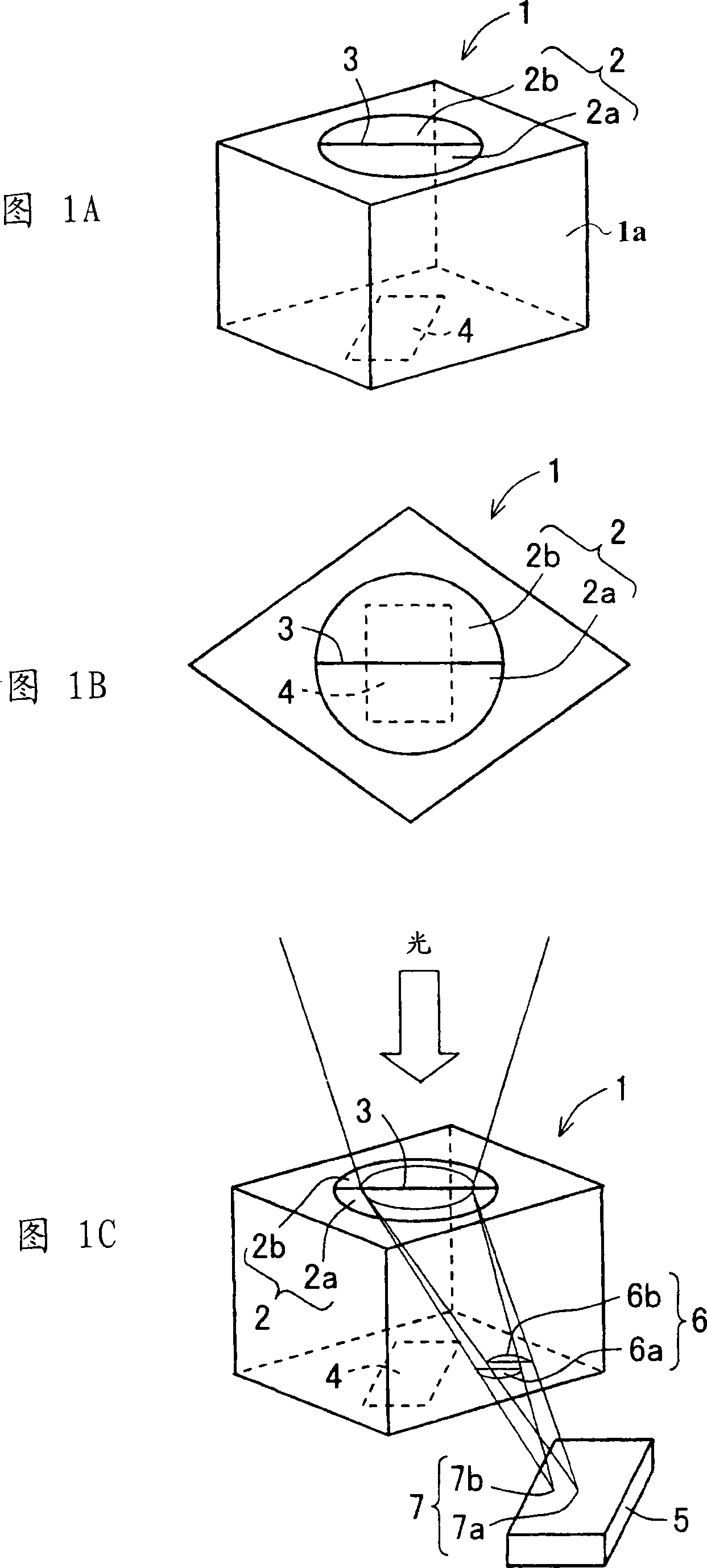
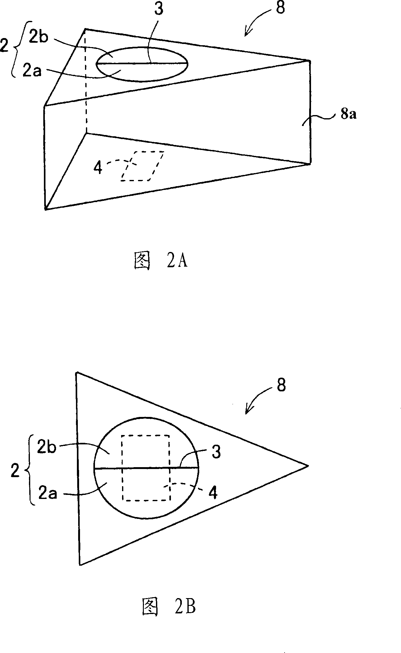
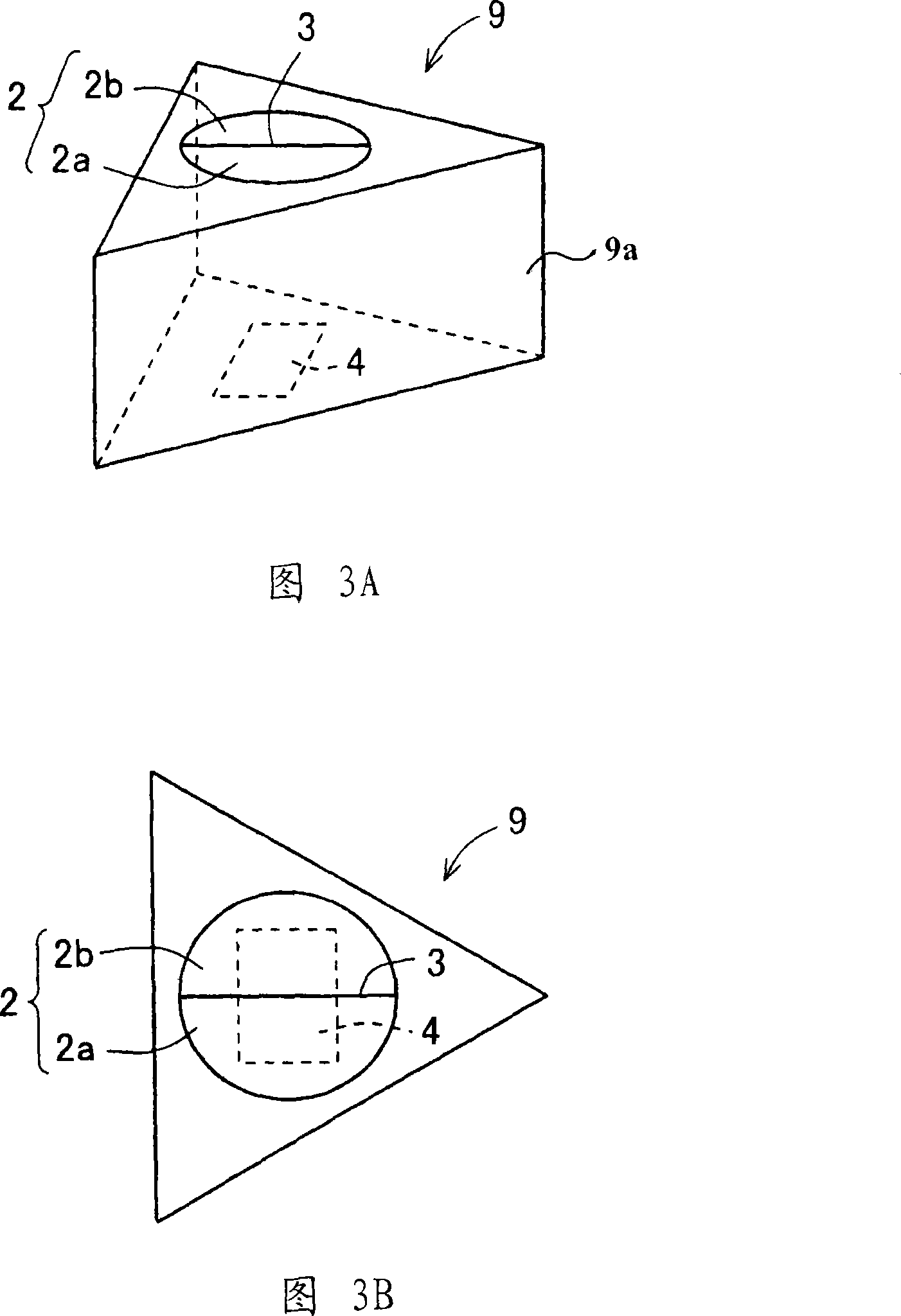
[0081] First, the minimum size required for a hologram element will be described.

[0082] The required minimum area of ​​the holographic surface is composed of the area of ​​the holographic area, the area area of ​​the grating surface by the first-order diffracted light of the light incident from the holographic surface as the signal light from the optical disc diffracted by the holographic area, and the area area of ​​the grating surface where the holographic element is fixed. When attaching to other optical parts, etc., the adhesive application area, that is, the contact area with other optical parts, etc., is determined.

[0083]In addition, the required minimum grating surface area consists of the area of ​​the grating, the area of ​​the grating surface used by the first-order diffracted light diffracted by the holographic region of the li...


PUM


Abstract

The present invention relates to a holographic element, a manufacturing method thereof, a holographic laser and an optical pickup using the holographic element. Provided is a holographic element that does not impair optical performance, is miniaturized, and has low manufacturing cost. The hologram element (1) is composed of a right columnar hologram element body (1a) having two rhombus-shaped bottom surfaces. A hologram region (2) divided by a dividing line (3) into a plurality of regions with different grating periods is provided on one bottom surface of a hologram element body (1a), and a grating (4) is provided on the other bottom surface. The length of the first diagonal line of the bottom surface is longer than the length of the second diagonal line. The center of the holographic area (2) is located at the intersection of the first diagonal and the second diagonal. The dividing line (3) is located on the first diagonal. Light incident from the bottom surface with the holographic area (2) is perpendicular to the bottom surface and is projected onto a plane containing the dividing line (3).

Description

[0001] technology area [0002] The present invention relates to a hologram element used in the manufacture of a semiconductor laser device which can be used in an optical pickup device or the like capable of reproducing, recording or erasing information on an information recording medium such as an optical disk. Background technique [0003] Semiconductor laser devices are used in optical pickup devices capable of reproducing, recording, or erasing information on information recording media such as CD (Compact Disk), MD (Mini Disc), or DVD (Digital Versatile Disk). In addition, in recent years, a laser device called a hologram laser has appeared, in which a semiconductor laser element, a hologram element, and a light-receiving element for signal detection are assembled in one package, and light is emitted from the semiconductor laser element and diffracted by the hologram element. The light reflected from the optical disk as an optical recording medium is guided to a light re...

Claims


Application Information

Patent Timeline
Patent Type & Authority Applications(China)
IPC IPC(8): G02B5/32G03H1/04G11B7/12
CPCG02B5/32
Inventor 熊谷宗乡
Owner SHARP KK
Why Eureka
Try Eureka