Separator for non-aqueous batteries, non-aqueous battery using same, and production method for separator for non-aqueous batteries

Inactive Publication Date: 2012-06-28
KURARAY CO LTD
View PDF0 Cites 42 Cited by
  • Summary
  • Abstract
  • Description
  • Claims
  • Application Information

AI Technical Summary

Benefits of technology

[0036]According to the present invention, it is possible to provide a non-aqueous battery having lower initial resistance, being capable of achieving higher output, and excelling in heat resistance while preventing short circuit generation by using a separator for non-aqueous batteries of the present invention.
[0037]Moreover, since the separator comprises a low melting-point polymer fiber layer formed of nanofibers and a heat-resistant polymer fiber layer comprising both nanofibers and non-nanofibers, even if a battery comprising the to separator is unusually heated, the low melting-point polymer can promptly melt to be a molten film to exhibit shutdown property. Accordingly, the shutdown performance of the ba

Problems solved by technology

However, these electrolyte solutions have a danger of ignition at a high temperature.
Furthermore, in the case where abnormal current flows in the non-aqueous batteries comprising above-mentioned materials by a short circuit or incorrect connection between positive and nega

Method used


Image

  • Separator for non-aqueous batteries, non-aqueous battery using same, and production method for separator for non-aqueous batteries
  • Separator for non-aqueous batteries, non-aqueous battery using same, and production method for separator for non-aqueous batteries

Examples


example 1

[0127](1) Production of Heat Resistant Polymer Fiber Layer (B)

[0128]Organic solvent-spun rayon fibers (“Tencel” (trademark) manufactured by Courtaulds; 1.7 dtex×3 mm) were beaten with a pulper and a fiberizer to be a fibrillated material having a CSF value of 0 mL. A slurry was prepared by using the above fibrillated material as a matrix fiber and ethylene-vinyl alcohol fibers (“S030” manufactured by Kuraray Co., Ltd.) as a binder fiber at a mass ratio of (matrix fiber):(binder fiber)=80:20.

[0129]Paper making of this slurry was carried out with a cylinder paper machine, then the resultant was dried with a dryer at a temperature of 130° C. to produce a heat-resistant polymer fiber layer with a basis weight of 10.9 g / m2 and a thickness of 15 μm.

[0130](2) Production of Low Melting-Point Polymer Fiber Layer (A)

[0131]Ethylene-vinyl alcohol copolymer (EVOH: “EVAL-G” manufactured by Kuraray Co., Ltd.) was added into DMSO solvent to dissolve in a still-standing state at a temperature of 25°...

example 2

[0134]Except for using polypropylene as a low melting-point polymer fiber layer instead of the ethylene-vinyl alcohol copolymer of Example 1, a separator was produced in the same way with Example 1.

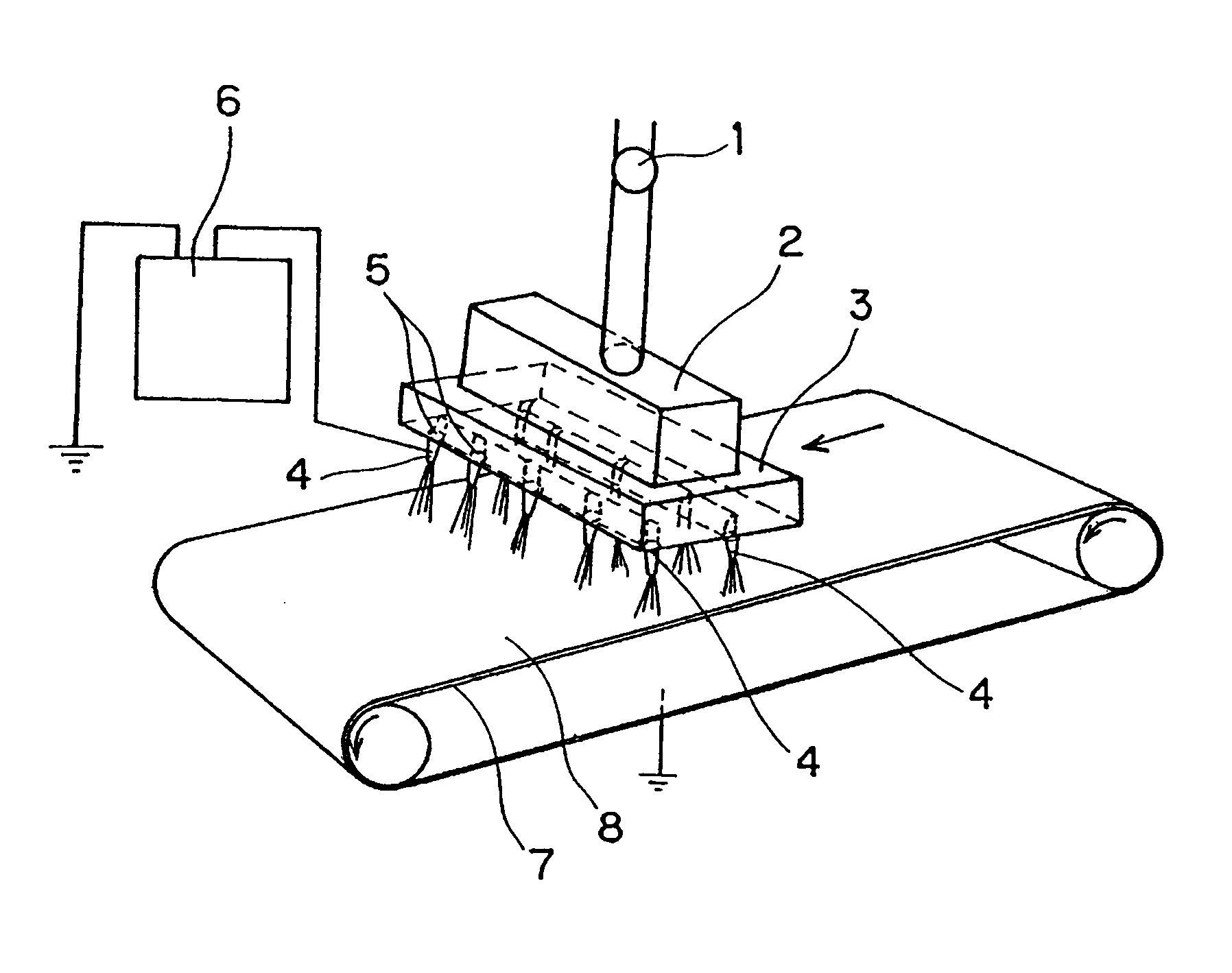
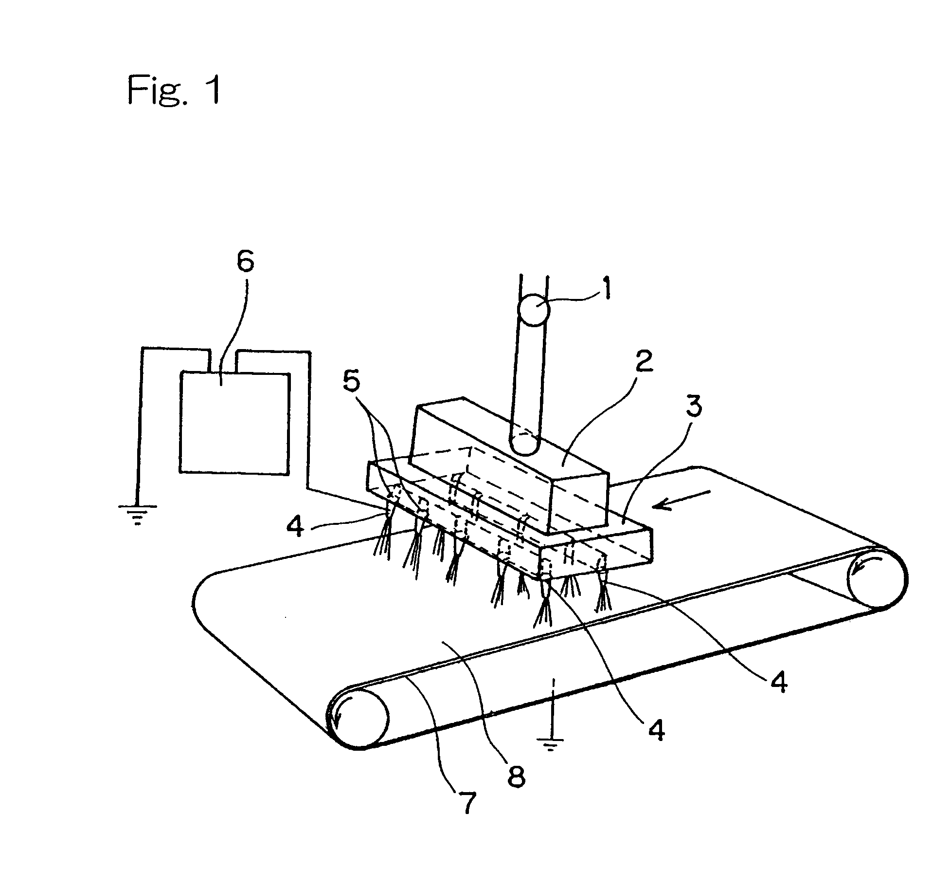
[0135]More specifically, the polypropylene (“B101” manufactured by Grand Polymer Co., Ltd.) was melt-kneaded at 300° C. with a twin-screw extruder to obtain a spinning liquid, then electro-spinning was carried out with the spinning machine of FIG. 1 type to produce low melting-point nanofibers.

[0136]The spinning machine comprises a needle having an inside diameter of 0.3 mm as the spinneret 4. The distance between the spinnerets 4 and the take-up device 7 was set to be 6 cm. The heat resistant polymer fiber layer obtained in the procedure of (1) of Example 1 was placed and wound up into the take-up device 7. Then, while moving the take-up device 7 at a conveyer speed of 0.1 m per minute, the spinning solution was extruded from the spinnerets 4 in a predetermined supply amount with applyin...

example 3

[0137]Except for using polyethylene (“5202B” manufactured by Mitsui Chemicals Inc.) instead of the low melting-point polymer of Example 2, a separator was produced in the same way with Example 2. The properties of thus obtained separator are shown in Table 1.


PUM

PropertyMeasurementUnit
Temperatureaaaaaaaaaa
Thicknessaaaaaaaaaa

Abstract

Provided is a separator for non-aqueous batteries not only having shutdown property but also achieving both higher output and short-circuit resistance. The separator comprising a laminate comprising: a low melting-point polymer fiber layer (A) having a melting point of 100 to 200° C., the low melting-point polymer fiber layer (A) comprising nanofibers having a fiber diameter of 1000 nm or smaller and formed from the low melting-point polymer; and a heat-resistant polymer fiber layer (B) positioned on the low melting-point polymer fiber layer (A) and comprising a high melting-point polymer having a melting point over 200° C. or a heat infusible polymer, the heat-resistant polymer fiber layer (B) comprising a mixture of nanofibers having a fiber diameter of 1000 nm or smaller and non-nanofibers having a fiber diameter over 1000 nm and both formed from heat-resistant polymer.

Description

CROSS REFERENCE TO THE RELATED APPLICATIONS[0001]This application is a continuation application, under 35 U.S.C. §111(a), of international application No. PCT / JP2010 / 065402, filed on Sep. 8, 2010, which claims priority to Japanese Patent Application No. 2009-214216, filed on Sep. 16, 2009, the entire disclosure of which is herein incorporated by reference in their entirety into this application.FIELD OF THE INVENTION[0002]The present invention relates to a separator for batteries useful as construction material of non-aqueous batteries and a non-aqueous battery using the same, and further relates to a method for producing the above-mentioned separator for batteries.BACKGROUND ART[0003]Recently, in order to adapt to cordless electrical and electric equipments, non-aqueous batteries, such as lithium batteries (lithium primary batteries) and lithium-ion secondary batteries (lithium-ion rechargeable batteries), have attracted attention as a power source with lightweight from which high ...

Claims


Application Information

Patent Timeline
IPC IPC(8): H01M2/16B05D1/12B32B38/00B82Y30/00H01M50/403H01M50/414H01M50/417H01M50/423H01M50/426H01M50/429H01M50/449H01M50/489
CPCH01M2/145H01M2/162Y02E60/12H01M10/05H01M2/1686Y02E60/10H01M50/44H01M50/403H01M50/449H01M50/429H01M50/417H01M50/414H01M50/489H01M50/426H01M50/423H01M2300/0017H01M50/411H01M50/463Y02P70/50
Inventor HAYAKAWA, TOMOHIROHAYASHI, HIDEOKAMADA, HIDEKIHOSOYA, TAKAYOSHIKAWAI, HIROYUKI
Owner KURARAY CO LTD
Why Eureka
Try Eureka