Light emitting diode package assembly that emulates the light pattern produced by an incandescent filament bulb

a technology of incandescent filament bulbs and package assemblies, which is applied in the direction of point-like light sources, semiconductor devices of light sources, lighting and heating apparatus, etc., can solve the problems of adding manufacturing and material costs, unable to achieve the desired 180 degree cone of light, and emitting only 90 degree cone of light. , to achieve the effect of efficient manufacturing

Active Publication Date: 2011-06-21
LIGHTING SCI GROUP
View PDF72 Cites 43 Cited by
  • Summary
  • Abstract
  • Description
  • Claims
  • Application Information

AI Technical Summary

Benefits of technology

[0004]In accordance with the invention, a light emitting diode package assembly is provided to emulate the pattern of light produced by an incandescent filament bulb. The package assembly is composed of a substrate for LEDs comprising a heat-sinking base having a pair of opposing major surfaces. Each major surface has overlying islands of electrically insulated but thermally conductive glass islands and an outer surface layer of electrically conductive reflective material. Disposed on each outer surface layer is a plurality of LEDs. The LEDs are arranged on the surface in a configuration of low mutual obstruction. Advantageously, reflecting elements transverse to each surface layer are positioned and shaped to reflect a substantial portion of the light emitted from the LEDs that would otherwise enter neighboring LEDs. In a preferred embodiment, the LEDs are arranged in the general form of a closed curve, and a transverse reflector is disposed in the interior of the curve. Alternatively, the LEDs can be arranged in a linear array. The assembly can be efficiently fabricated by back-to-back assembly of two similar subassemblies.

Problems solved by technology

However, basic LEDs emit only a 90 degree cone of light.
However, these techniques include cumbersome optics and add manufacturing and material costs without achieving the desired 180 to −180 degree viewing angle.
A packaging challenge arises because the package must both conduct heat away from the LEDs and at the same time permit unobstructed emission.
Similarly when multiple LEDs are placed adjacent each other on a substrate, photons reflected between adjacent diodes are never recovered.
When the LEDs are placed in rows and columns inside a cavity or on a planar conductive substrate, there is a significant photon absorbance and obstruction by the adjacent dies.

Method used


Image

  • Light emitting diode package assembly that emulates the light pattern produced by an incandescent filament bulb
  • Light emitting diode package assembly that emulates the light pattern produced by an incandescent filament bulb
  • Light emitting diode package assembly that emulates the light pattern produced by an incandescent filament bulb

Examples


Embodiment Construction

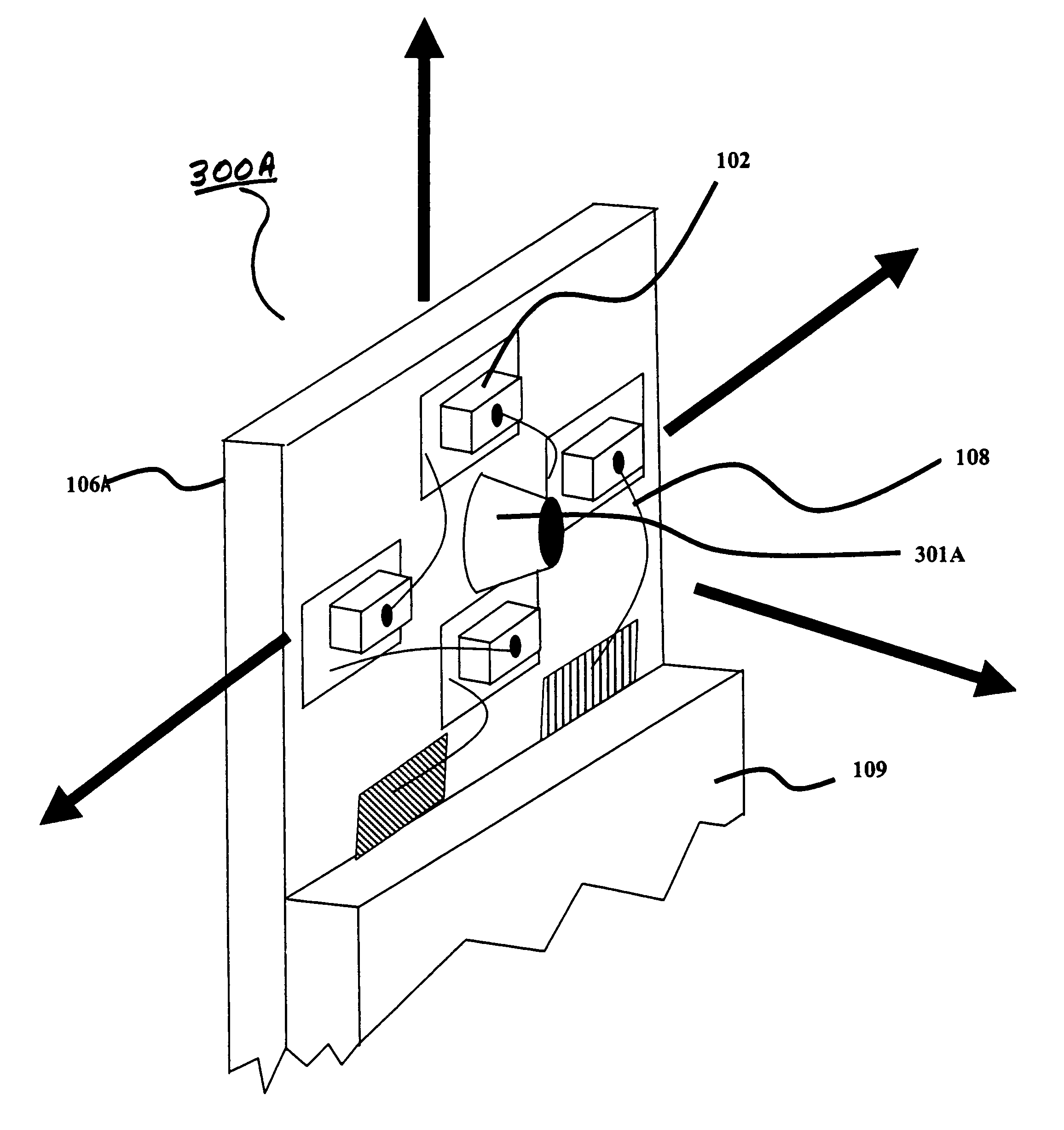
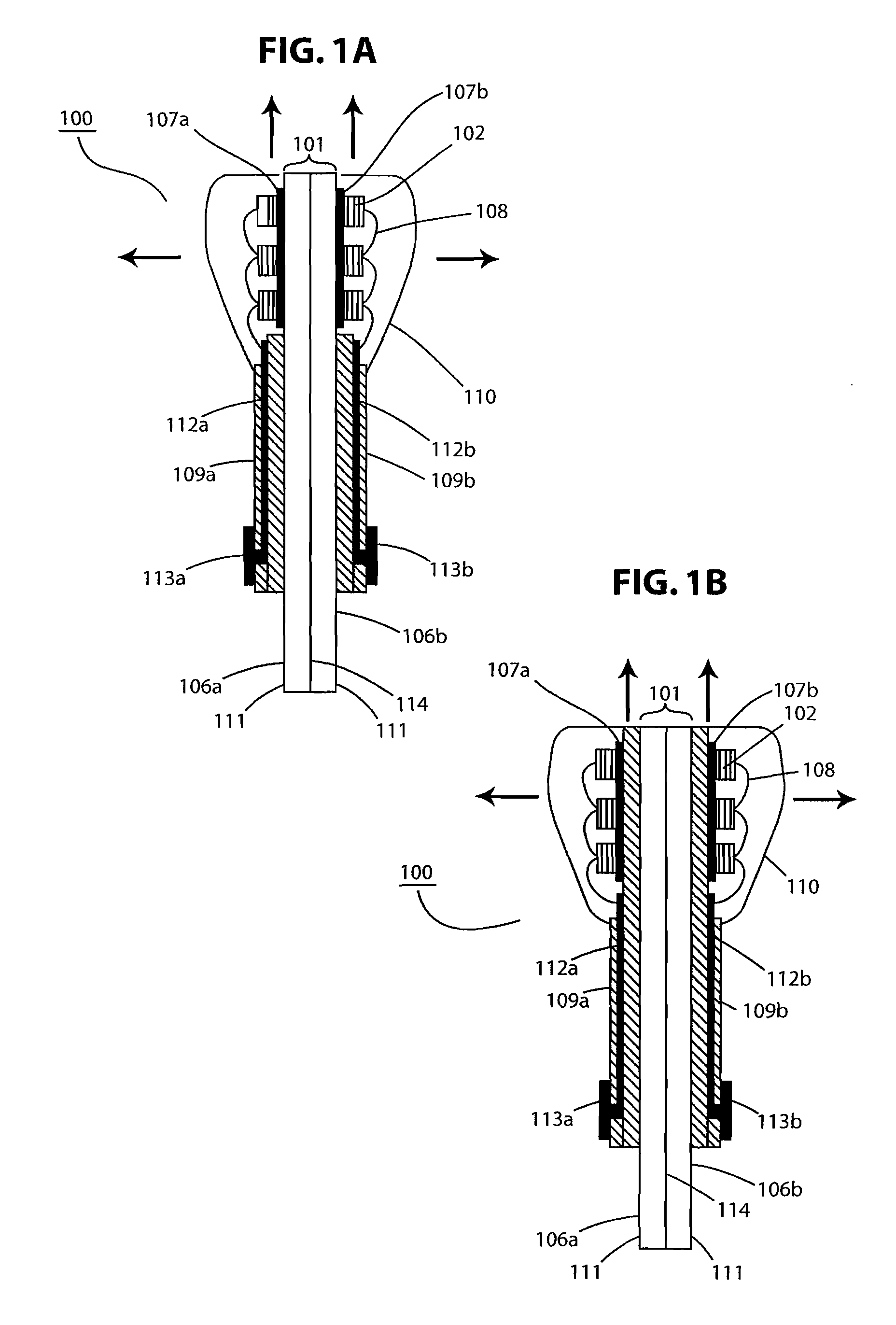
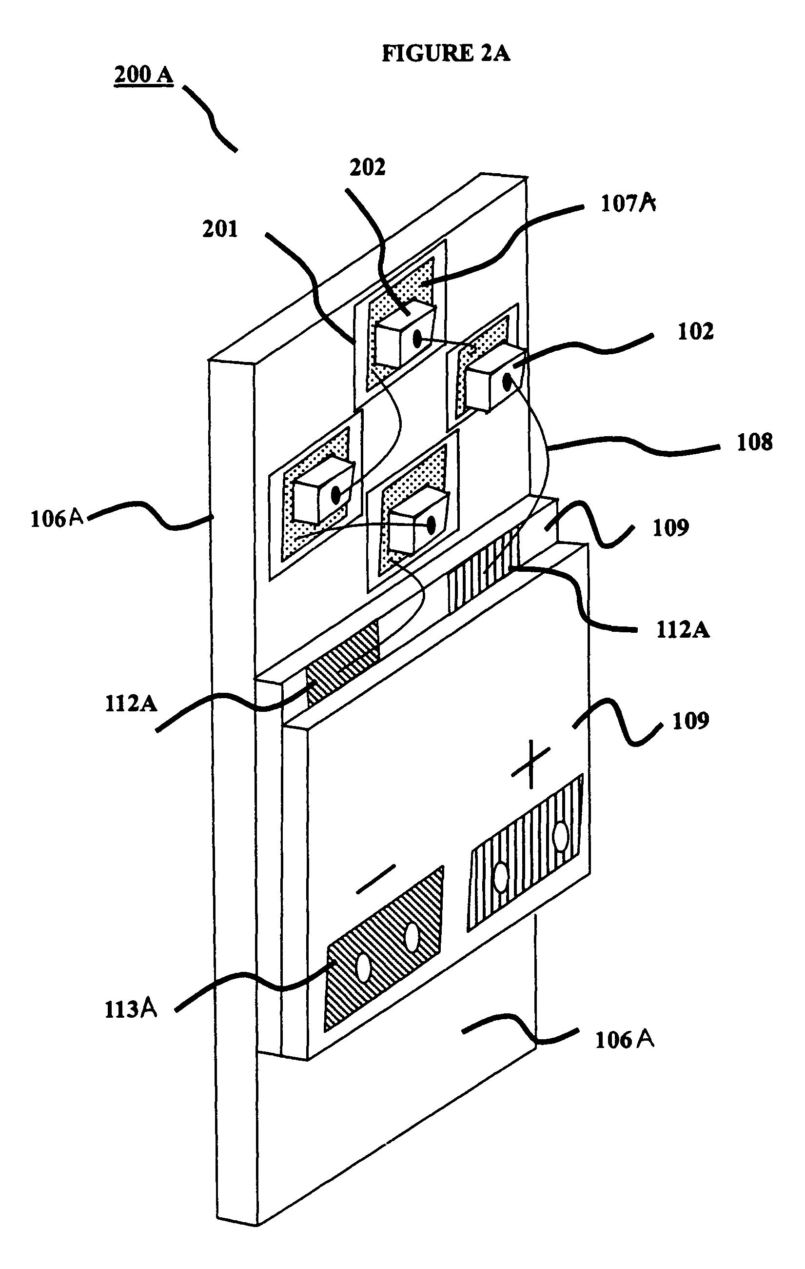
[0011]Referring to the drawings, FIGS. 1A and 1B are schematic cross sections of exemplary LED package assemblies 100 for emulating the pattern of light produced by an incandescent filament bulb. The package assembly 100 is composed of a pair of substrates 106A, 106B, each supporting a plurality of LEDs 102. The substrates 106A, 106B are placed in back-to-back adjacency and thermally coupled to form a heat sinking base 101 having a pair of opposing major support surfaces 111. Each of the major surfaces is advantageously composed of an overlying dielectric layer 109 (e.g., a ceramic layer) and an outer surface layer 107A, 107B of light reflecting material such as a specularly reflecting metal film over a glass layer. FIG. 1A shows the outer surface layers 107A, 107B directly overlying the heat sinking base 101, and FIG. 1B shows the outer surface layers 107A, 107B overlying the dielectric layers 109A, 109B, respectively. According to an embodiment of the present invention, the overly...


PUM


Abstract

In accordance with the invention, a light emitting diode package assembly is provided to emulate the pattern of light produced by an incandescent filament bulb. The package assembly is composed of a substrate for LEDs comprising a heat-sinking base having a pair of opposing major surfaces. Each major surface has an overlying of thermally conducting ceramic and an outer surface layer of light reflective material. Disposed on each surface layer is a plurality of LEDs. Advantageously, the LEDs are arranged on the surface in a configuration of low mutual obstruction. Advantageously, reflecting elements transverse to each surface layer are positioned and shaped to reflect a substantial portion of the light emitted from the LEDs that would otherwise enter neighboring LEDs. In a preferred embodiment, the LEDs are arranged in the general form of a closed curve, and a transverse reflector is disposed in the interior of the curve. Alternatively, the LEDs can be arranged in a linear array. The assembly can be efficiently fabricated by back-to-back assembly of two similar subassemblies.

Description

BACKGROUND OF THE INVENTION[0001]Increases in luminous efficiencies and diode luminous intensity have made possible the use light emitting diodes (LEDs) for general lighting and illumination applications. As the efficiency and intensity of high brightness LED devices (HB LEDs) approaches those of incandescent light sources, the packaging of LEDs for general lighting and control of the light radiation patterns and spectral viewing angles becomes increasingly important. In order to replace a tungsten filament bulb, a diode package must facilitate heat dissipation and expand both the luminous viewing angle and the radiation pattern.[0002]Incandescent filament light bulbs emit light at angles in the range 180 to −180 degrees about the bulb. However, basic LEDs emit only a 90 degree cone of light. Various techniques such as diffusion on the LEDs and combining plural LEDs have increased the viewing angle. See for example, U.S. Pat. No. 5,122,781 to Saubolle and U.S. Pat. No. 5,140,220 to ...

Claims


Application Information

Patent Timeline
Patent Type & Authority Patents(United States)
IPC IPC(8): H01L33/00F21K99/00H01L29/24
CPCF21K9/00F21V29/89F21V29/70H05K1/053H01L2224/45144F21Y2101/02H01L2924/19107H01L2224/48465H01L2224/48091H01L2924/00014H01L2924/00F21Y2115/10F21Y2107/90F21K9/68
Inventor MAZZOCHETTE, JOSEPHAMAYA, EDMARLI, LINBLONDER, GREG E.
Owner LIGHTING SCI GROUP
Why Eureka
Try Eureka