B-type LNG ship enclosure system

An LNG ship and hull technology, which is applied in the direction of ship hull, ship construction, and some cabins in the hull, etc., can solve the construction and design workload of increasing the use area of ​​low-temperature materials, insufficient clearance between the containment system and the hull structure, and increase the risk of low-temperature liquid leakage and other problems, to achieve the effect of saving peripheral clearance, reducing the scope of use, and reducing the evaporation rate of liquid cargo

Active Publication Date: 2019-04-05
HUDONG ZHONGHUA SHIPBUILDINGGROUP
View PDF6 Cites 0 Cited by
  • Summary
  • Abstract
  • Description
  • Claims
  • Application Information

AI Technical Summary

Problems solved by technology

When a ship sails at sea, affected by waves, it will produce hull motion states such as roll, pitch, and heave, and cause relative motion between the relatively independent containment system and the hull structure. Sloshing, more serious may cause damage to the containment system, damage the external insulation layer, and cause leakage of cryogenic liquid
[0004] In order to avoid the above problems, it is necessary to set up vertical support devices, anti-sway support devices, and anti-pitch support devices on the periphery of the containment system to support the self-weight of the containment system and resist lateral and longitudinal relative movements, usually requiring a large number of supports device, which will lead to insufficient clearance between the containment system and the hull structure, increasing the difficulty of subsequent construction and maintenance
[0005] At the same time, the arrangement of the supporting device leads to poor integrity of the external insulation layer, increasing the risk of cryogenic liquid leakage
In addition, due to the low-temperature conduction of the support device, the temperature near the hull structure connected to it is relatively low, and the excessive number of support devices increases the use area of ​​low-temperature materials and the workload of construction design

Method used


Image

  • B-type LNG ship enclosure system
  • B-type LNG ship enclosure system
  • B-type LNG ship enclosure system

Examples


Embodiment Construction

[0032] In order to make the object, technical solution and advantages of the present invention clearer, the present invention is described below through specific embodiments shown in the accompanying drawings. It should be understood, however, that these descriptions are exemplary only and are not intended to limit the scope of the present invention. Also, in the following description, descriptions of well-known structures and techniques are omitted to avoid unnecessarily obscuring the concept of the present invention.

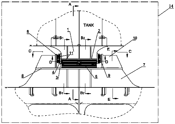
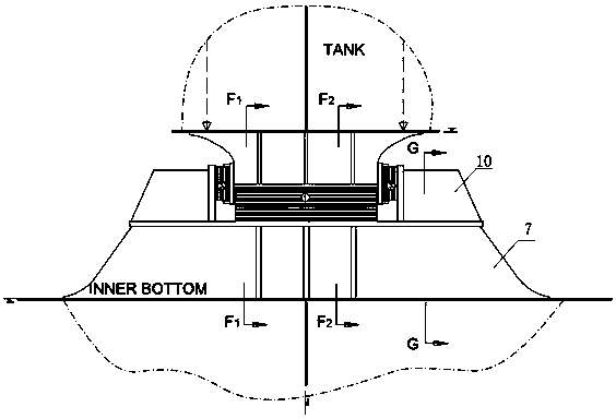
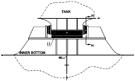
[0033] combine Figure 1-Figure 9 To illustrate this embodiment, the B-type LNG ship containment system support device of the present invention includes a lower support base, an upper support base, an intermediate pressure-bearing wood 5, a lower lateral support assembly, an upper lateral support assembly and an outer pressure-bearing wood 6. The lower support base is fixed on the hull structure, the upper support base is fixed on the bottom of the liquid car...


PUM


Abstract

The invention discloses a B-type LNG ship enclosure system and a support device thereof. The support device includes a lower support seat, an upper support seat, an intermediate bearing wood disposedbetween the lower support seat and the upper support seat, lower lateral support assemblies fixed to the upper surface of the lower support seat, upper lateral support assemblies disposed on the peripheral surface of the intermediate bearing wood, and an outer-layer bearing wood, the outer-layer bearing wood is fixed between the lower lateral support assemblies and the upper lateral support assemblies, and a low-temperature resistant epoxy resin layer is arranged between the contact surfaces of the outer-layer bearing wood and the upper lateral support assemblies, and between the contact surfaces of the outer-layer bearing wood, and the upper support seat and the upper lateral support assemblies respectively. The B-type LNG ship enclosure system can simultaneously transmit loads in the longitudinal, transverse and vertical directions, effectively restricts the movement of the liquid cargo enclosure system in the transverse, longitudinal and vertical directions, and effectively reducesthe liquid cargo evaporation rate.

Description

technical field [0001] The patent application for this invention is a divisional application of the patent application 201810341672.7 on April 17, 2018. [0002] The invention relates to the technical field of shipbuilding, in particular to a B-type LNG ship containment system and a supporting device thereof. Background technique [0003] The structural material of the type B independent liquid cargo tank is 9Ni steel, and the periphery is covered with a polyurethane insulating layer. Unlike the membrane type LNG carrier, its liquid cargo tank is supported by the hull support device structure. When a ship sails at sea, affected by waves, it will produce hull motion states such as roll, pitch, and heave, and cause relative motion between the relatively independent containment system and the hull structure. Sloshing, in more serious cases, may cause damage to the containment system, damage the external insulation layer, and cause leakage of cryogenic liquid. [0004] In orde...

Claims


Application Information

Patent Timeline
Patent Type & Authority Applications(China)
IPC IPC(8): B63B11/00
CPCB63B11/00
Inventor 刘金峰杨仁记王佳颖万忠
Owner HUDONG ZHONGHUA SHIPBUILDINGGROUP
Why Eureka
Try Eureka