Trolley lifting mechanism used for carrying surgical tools

A lifting mechanism and trolley technology, applied in the field of medical devices, can solve the problems of poor stability and large eccentric load, and achieve the effects of reducing force, running smoothly, and improving stability

Active Publication Date: 2019-04-05
BEIJING SURGERII TECH CO LTD
View PDF16 Cites 6 Cited by
  • Summary
  • Abstract
  • Description
  • Claims
  • Application Information

AI Technical Summary

Problems solved by technology

[0003] The object of the present invention is to provide a trolley lifting mechanism for carrying surgical tools, to solve the problems of large eccentric load and poor stability in the trolley lifting mechanism for carrying surgical tools in surgical robots

Method used


Image

  • Trolley lifting mechanism used for carrying surgical tools
  • Trolley lifting mechanism used for carrying surgical tools
  • Trolley lifting mechanism used for carrying surgical tools

Examples


Embodiment 1

[0030] Embodiment 1 provides a trolley lifting mechanism for carrying surgical tools, and its structure will be described in detail below.

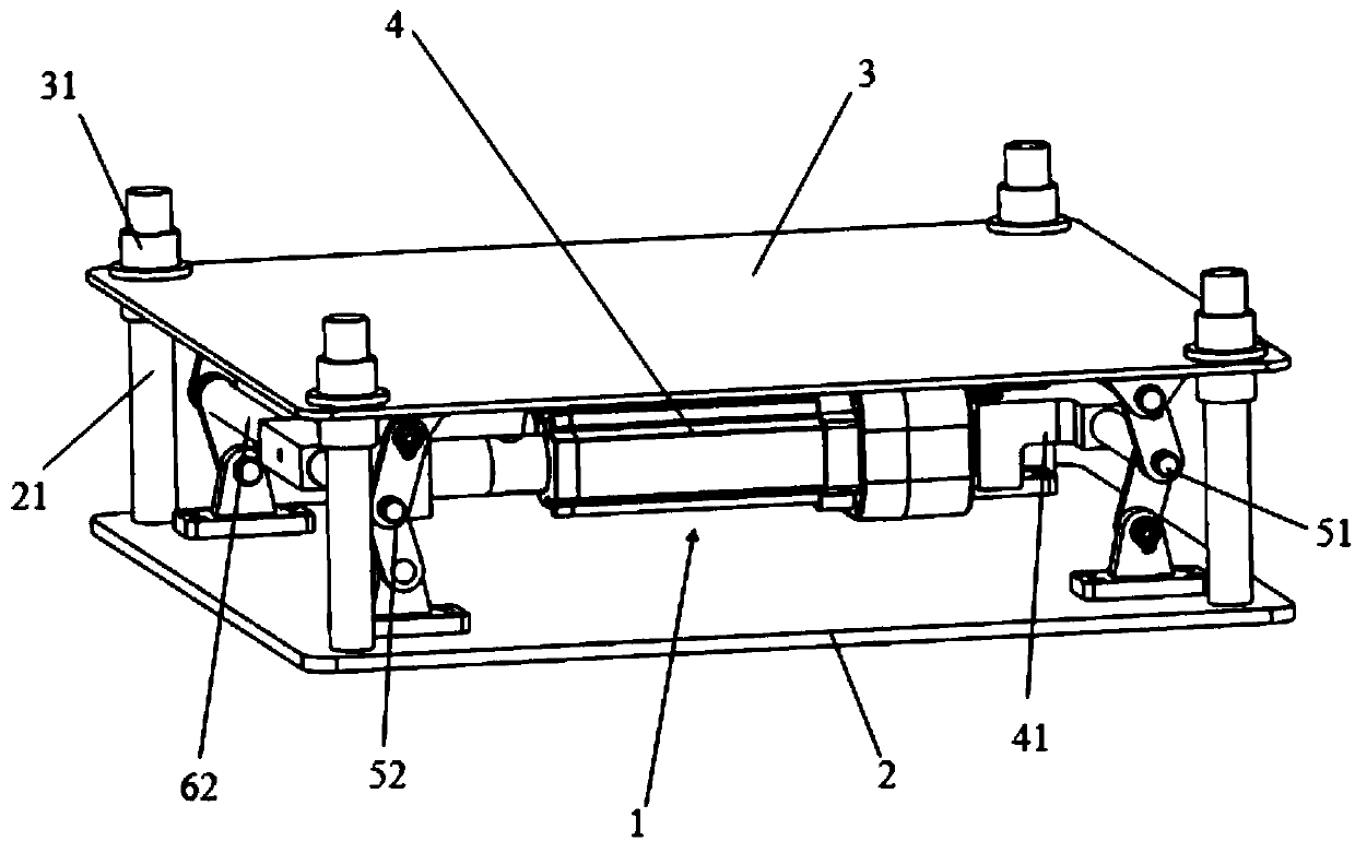
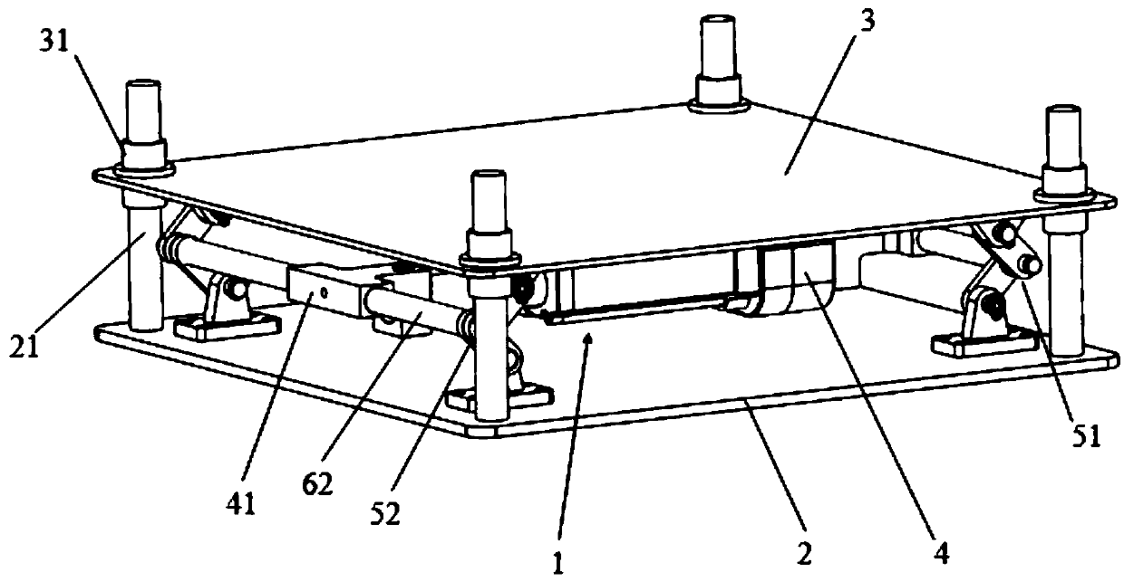
[0031] refer to figure 1 and figure 2 , the trolley lifting mechanism includes a connecting rod lifting mechanism 1, a lower plate 2, an upper plate 3 and an electric push rod 4, and the lower plate 2 is set on a support plane, which can be a flat ground, a floor surface, a desktop, etc. The lower plate 2 is parallel to the upper plate 3, four guide rods 21 are vertically fixed on the lower plate 2, and the connection lines of the projection points of the four guide rods 21 on the lower plate 2 are rectangular, and four guide rods 21 are vertically fixed on the upper plate 3. Cover 31, the connection line of the projection points of four guide sleeves 31 on the upper plate 3 is a rectangle, the guide rod 21 is a straight rod, the two ends of the guide sleeve 31 are open, and the four guide rods 21 are respectively installed on the four ...

Embodiment 2

[0041] In order to further improve the stability of the trolley lifting mechanism, on the basis of Embodiment 1, Embodiment 2 improves the hinge 80 and its connection relationship. The improvements are as follows:

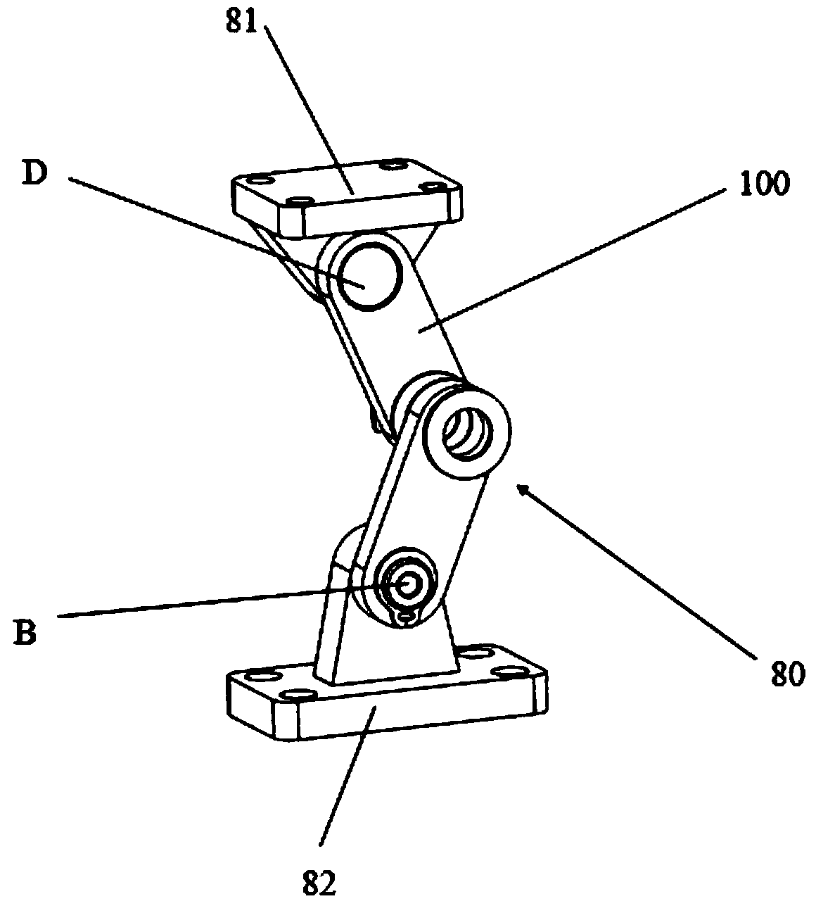
[0042] refer to Figure 6 , the hinge 80 includes four jacking rods 100, the hinge 80 is connected end to end by the four jacking rods 100 to form a parallelogram, and the two adjacent jacking rods 100 at the upper part are hinged through the upper hinge hole D, and the two lower Adjacent jacking rods 100 are hinged through lower hinge holes B, two adjacent jacking rods 100 on the left are hinged through outer hinge holes A, and two adjacent jacking rods 100 on the right are hinged through inner hinge holes C.

[0043] refer to Figure 7 , the settings of the left force beam 62 and the right force beam 61 are selected from one of the following two ways:

[0044] In the first type, the two ends of the right force transmission beam 61 are respectively penetrated in...

Embodiment 3

[0047] In order to further improve the stability of the lifting mechanism of the trolley, on the basis of Embodiment 2, Embodiment 3 improves the connection relationship between the hinges. The improvements are as follows:

[0048] refer to Figure 8 to Figure 11 , the link lifting mechanism 1 also includes a first front stabilizer bar 71, a second front stabilizer bar 72, a first rear stabilizer bar 73 and a second rear stabilizer bar 74,

[0049] The inner hinge hole C of the first hinge part 51 on one side is connected with the outer hinge hole A of the second hinge part 52 through the first front stabilizer bar 71, and the outer hinge hole A of the first hinge part 51 on the same side is connected with the second hinge hole A. The inner hinge hole C of the member 52 is connected through the second front stabilizer bar 72;

[0050] The inner hinge hole C of the first hinge part 51 on the other side is connected with the outer hinge hole A of the second hinge part 52 throug...


PUM


Abstract

The invention discloses a trolley lifting mechanism used for carrying surgical tools. The trolley lifting mechanism comprises a connecting rod lifting mechanism, an upper flat plate, a guide rod and an electric pushing rod, wherein the connecting rod lifting mechanism comprises four hinged parts, a left force transmission beam and a right force transmission beam; each hinged part comprises an upper hinge support base, a lower hinge support base and a hinge, wherein the hinge is arranged between the upper hinge support base and the lower hinge support base; the connecting rod lifting mechanismis fixedly arranged on the supporting plane through four lower hinge support bases, and is fixedly arranged on the upper flat plate through four upper hinge support bases; and the two ends of the electric pushing rod are separately arranged on the left force transmission beam and the right force transmission beam in a sleeving mode, and can freely move along the axial directions of the force transmission arms. The trolley lifting mechanism disclosed by the invention is compact in structure, realizes multi-point jacking and is good in stability; the electric pushing rod can horizontally move along the axis of the left force transmission arm and the axis of the right force transmission arm to reduce eccentric load amount at the two sides, so that mechanism lifting is more stable, a medical trolley can be stressed uniformly and reasonably ascended and descended, and requirements in aspect of spatial size of the medical trolley are met.

Description

technical field [0001] The invention relates to the technical field of medical instruments, in particular to a trolley lifting mechanism for carrying surgical tools. Background technique [0002] In recent years, my country's surgical robot market has developed rapidly, and research and development of various neural robots, orthopedic robots, and laparoscopic robots have emerged in an endless stream. affected area. However, the current trolley lifting mechanism has a large eccentric load and poor stability, which cannot meet the high requirements of medical operations on the stability of the lifting trolley. Contents of the invention [0003] The object of the present invention is to provide a trolley elevating mechanism for carrying surgical tools to solve the problems of large eccentric load and poor stability in the trolley lifting mechanism for carrying surgical tools in a surgical robot. [0004] The present invention provides a trolley lifting mechanism for carrying...

Claims


Application Information

Patent Timeline
Patent Type & Authority Applications(China)
IPC IPC(8): B66F7/06B66F7/28A61B50/26
CPCA61B50/26B66F7/0641B66F7/28Y02T10/70
Inventor 徐凯马铁宁
Owner BEIJING SURGERII TECH CO LTD
Why Eureka
Try Eureka