Dedusting screen window with temperature adjusting function
A technology of temperature adjustment and function, which is applied in the field of doors and windows, can solve the problems of inconvenience of people’s life, the infringement of residents’ smog and dust, single function, etc., and achieve the effect of increasing the relative moving range and improving the adsorption capacity
- Summary
- Abstract
- Description
- Claims
- Application Information
AI Technical Summary
Problems solved by technology
Method used
Image

Examples
Embodiment 1
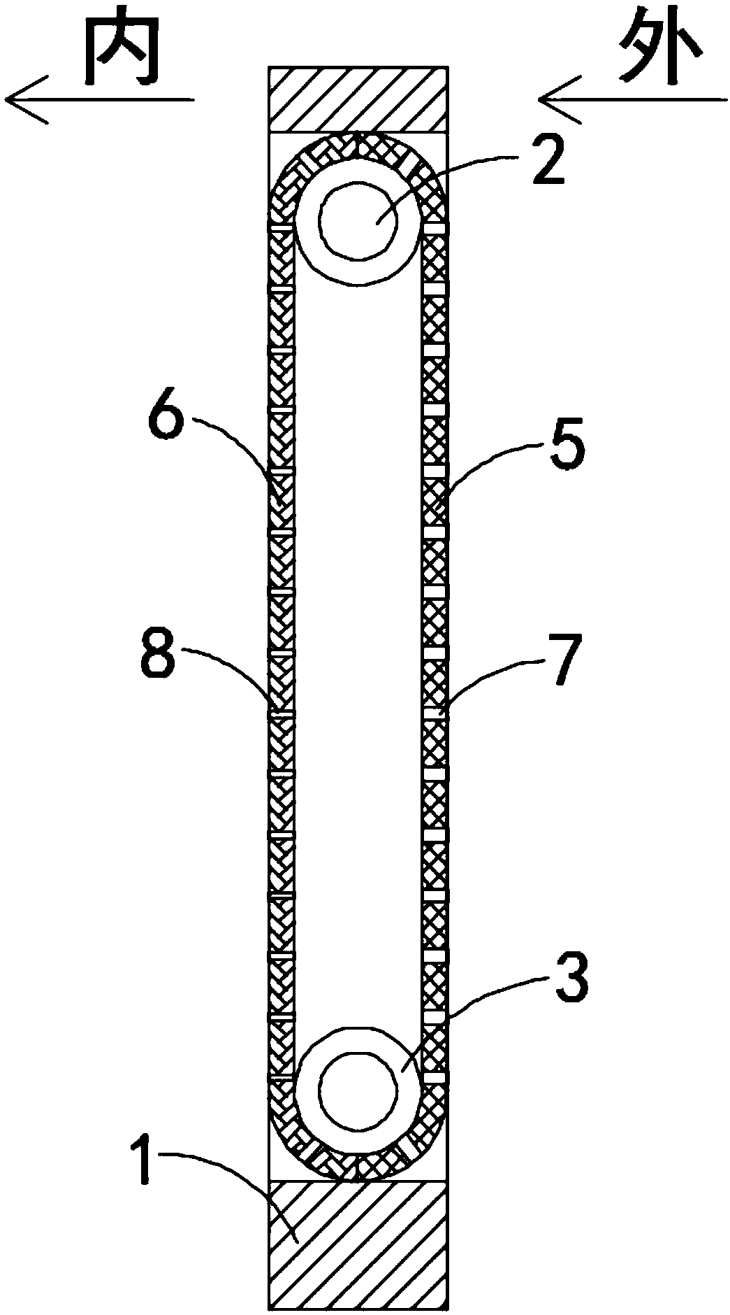
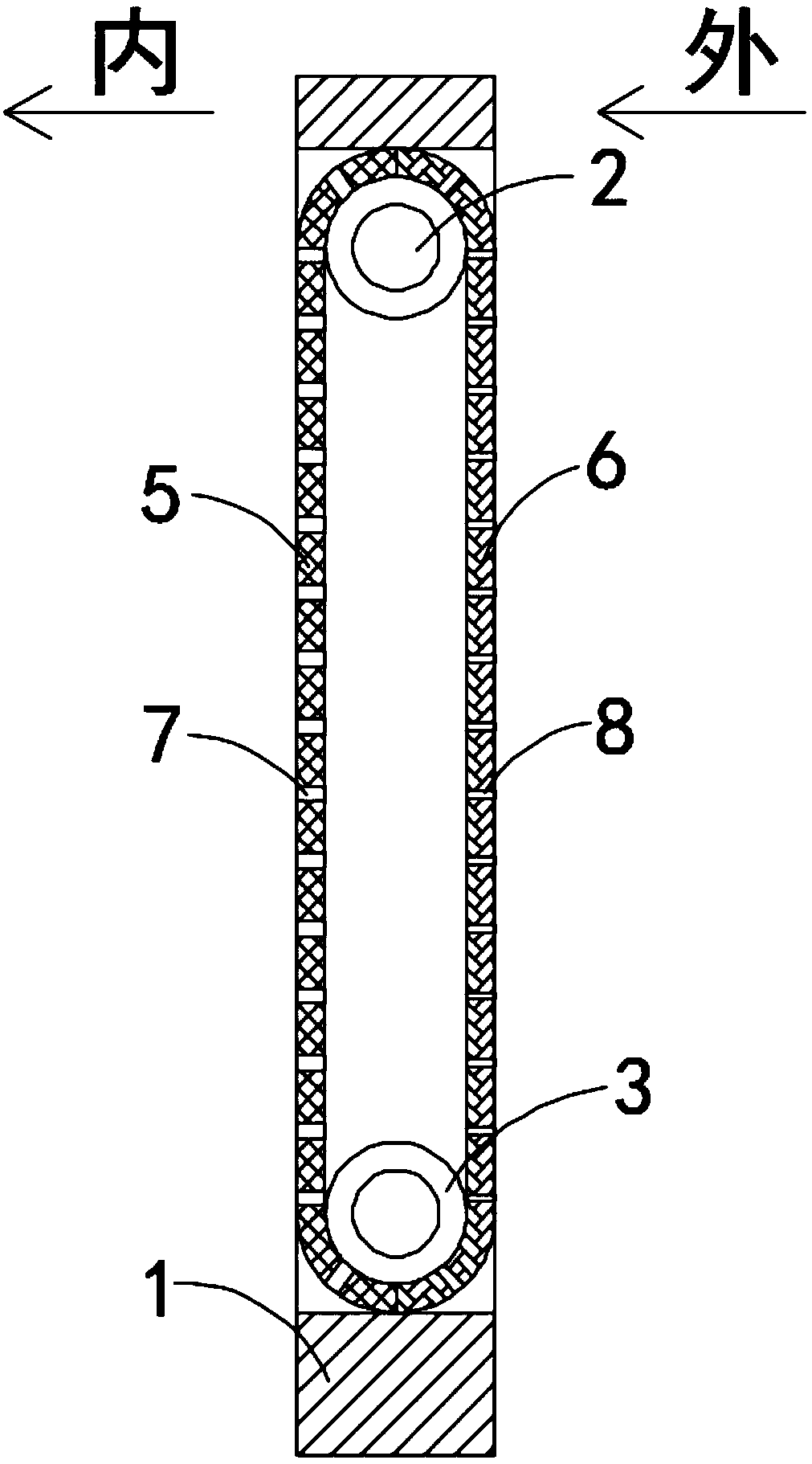
[0021] like Figure 1-2 As shown, a dust-removing screen window with temperature adjustment function includes a window frame 1, and two upper and lower rotating shafts 2 arranged horizontally are fixedly connected in the window frame 1. The two rotating shafts 2 are located in the same vertical plane, and the rotating shafts 2 are connected by rotation. There is a rotating cylinder 3, and it should be noted that the rotating cylinder 3 is rotationally connected with the rotating shaft 2 through a plurality of damping bearings, and the two rotating cylinders 3 are wound with a gauze belt 4, and the gauze belt 4 is composed of a first gauze of equal length The first gauze bar 5 and the second gauze bar 6 are spliced together, and the ends of the first gauze bar 5 and the second gauze bar 6 are woven together, and the first gauze bar 5 is evenly distributed with a plurality of first air-permeable Holes 7 and the second gauze bar 6 are evenly distributed with a plurality of seco...
Embodiment 2
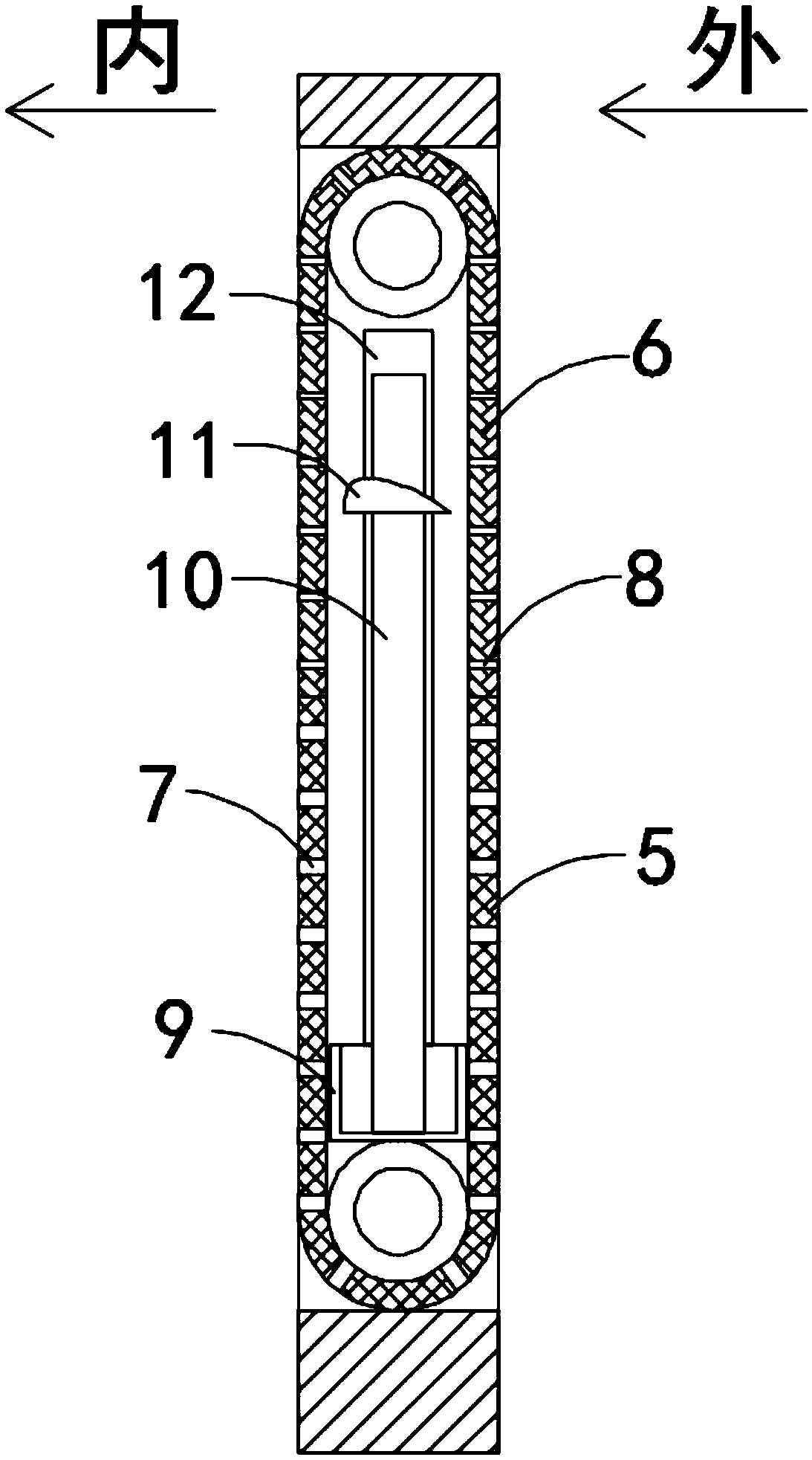
[0027] like Figure 3-5 As shown, the difference between this embodiment and Embodiment 1 is that the dust removal mechanism includes a dust collection box 9 fixedly connected to the inner wall of the window frame 1, and a plurality of electrostatic risers arranged side by side are fixedly connected in the dust collection box 9 10. A plurality of static vertical plates 10 are covered with the same movable friction block 11 that can move up and down in the vertical direction. It should be noted that the upper edge of the cross section of the movable friction block 11 is streamlined, and the cross section of the movable friction block 11 is The lower edge is a straight line, and the movable friction block 11 is in the shape of a wing plate as a whole. Fixed friction columns 12 are fixedly connected to the inner walls of both sides of the window frame 1. The movable friction block 11 is made of a light foam block wrapped with a silk layer. A glass plate is embedded on the side wa...
PUM
 Abstract
Description
Claims
Application Information
 - R&D
- Intellectual Property
- Life Sciences
- Materials
- Tech Scout
- Unparalleled Data Quality
- Higher Quality Content
- 60% Fewer Hallucinations
Browse by: Latest US Patents, China's latest patents, Technical Efficacy Thesaurus, Application Domain, Technology Topic, Popular Technical Reports.
© 2025 PatSnap. All rights reserved.Legal|Privacy policy|Modern Slavery Act Transparency Statement|Sitemap|About US| Contact US: help@patsnap.com