Check patentability & draft patents in minutes with Patsnap Eureka AI!

Bolt locking structure

A locking structure and bolt technology, applied in the direction of bolts, screws, nuts, etc., can solve the problems of small application range and poor welding performance, and achieve the effect of wide application range and avoiding loosening.

Pending Publication Date: 2019-04-05
STATE GRID CORP OF CHINA +3
View PDF0 Cites 2 Cited by
  • Summary
  • Abstract
  • Description
  • Claims
  • Application Information

AI Technical Summary

Problems solved by technology

However, these two locking methods have their own limitations
The washer lock can only lock the bolts and nuts installed on the edge of the workpiece, and its use is limited by the installation position; while the stopper lock requires welding on the workpiece. Some workpieces are made of high-strength and high-carbon steel, and the welding performance Poor, its use is limited by the material of the workpiece; the scope of application of both is small
[0003] Therefore, existing locking mode of bolt or nut has the problem of small scope of application

Method used


Image

  • Bolt locking structure
  • Bolt locking structure
  • Bolt locking structure

Examples


Embodiment 1

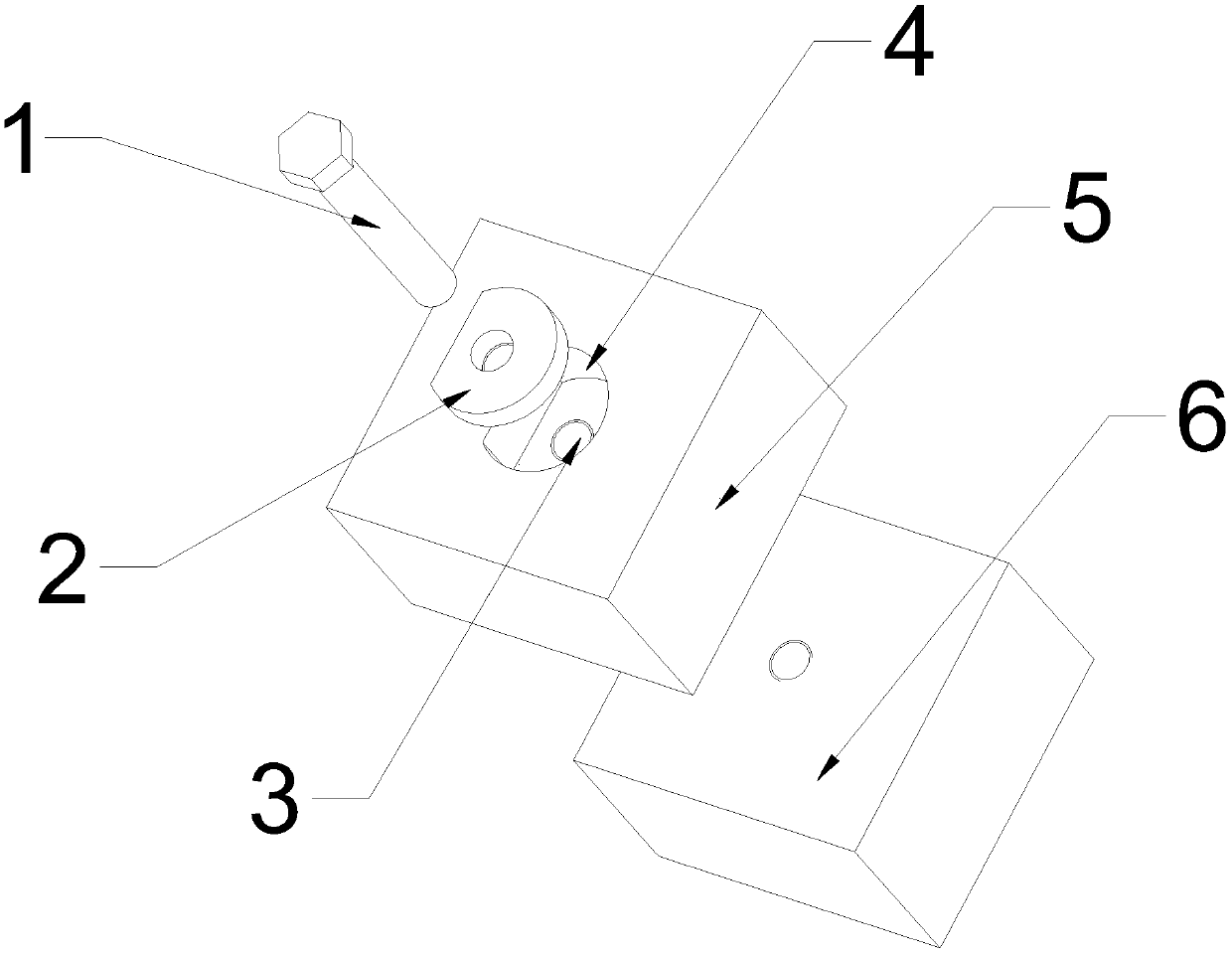
[0015] Example 1. A bolt locking structure constituted as figure 1 As shown, it includes the countersunk threaded through hole arranged on the upper workpiece, and the countersunk threaded through hole includes an upper special-shaped countersunk head 4 and a lower threaded part 3; The upper special-shaped countersunk head 4 is matched; the bolt 1 is connected with the upper special-shaped countersunk head 4 and the lower threaded part 3 through the special-shaped washer 2; the bolt 1 and the special-shaped washer 2 are welded and fixed. The bolt 1 passes through the special-shaped washer 2 and connects the upper workpiece 5 and the lower workpiece 6; the countersunk threaded through hole includes the upper special-shaped countersunk head 4 above the upper workpiece 5 and the lower threaded part 3 below the upper workpiece 5, and the upper special-shaped countersunk head 4 is used to fix the special-shaped washer 2, and the shape and size of the special-shaped washer 2 match ...

Embodiment 2

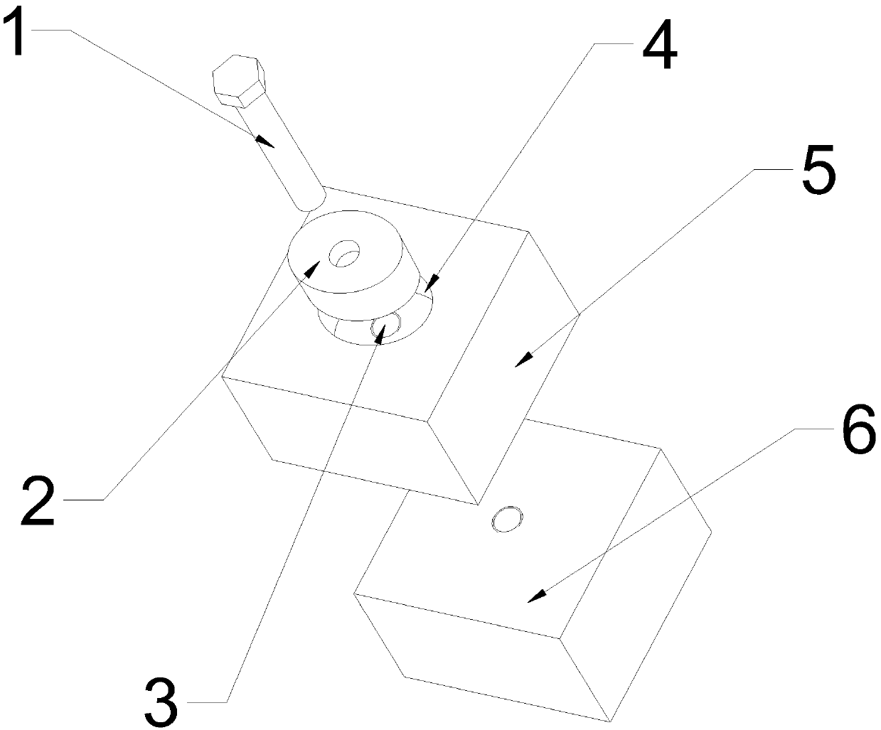
[0019] Example 2. A bolt locking structure constituted as figure 2 As shown, it includes the countersunk threaded through hole arranged on the upper workpiece, and the countersunk threaded through hole includes an upper special-shaped countersunk head 4 and a lower threaded part 3; The upper special-shaped countersunk head 4 is matched; the bolt 1 is connected with the upper special-shaped countersunk head 4 and the lower threaded part 3 through the special-shaped washer 2; the bolt 1 and the special-shaped washer 2 are welded and fixed.

[0020] The special-shaped washer 2 is a low carbon steel washer.

[0021] The special-shaped washer 2 is welded and fixed to one side of the bolt 1 .

[0022] The upper special-shaped countersunk head 4 is an oval countersunk head.

Embodiment 3

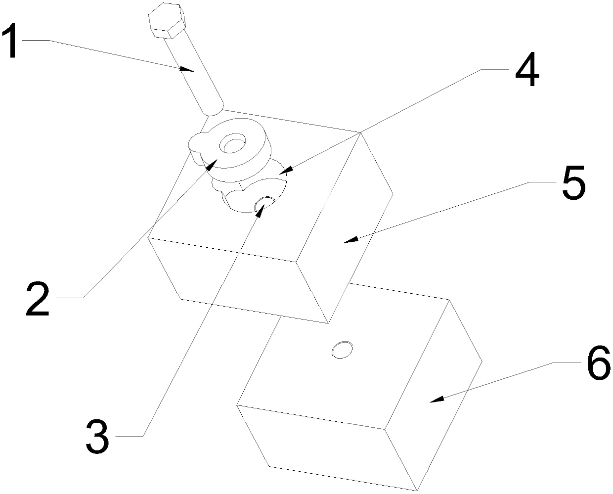
[0023] Example 3. A bolt locking structure constituted as image 3 As shown, it includes the countersunk threaded through hole arranged on the upper workpiece, and the countersunk threaded through hole includes an upper special-shaped countersunk head 4 and a lower threaded part 3; The upper special-shaped countersunk head 4 is matched; the bolt 1 is connected with the upper special-shaped countersunk head 4 and the lower threaded part 3 through the special-shaped washer 2; the bolt 1 and the special-shaped washer 2 are welded and fixed.

[0024] The special-shaped washer 2 is a low carbon steel washer.

[0025] The special-shaped washer 2 is welded and fixed to one side of the bolt 1 .

[0026] The upper special-shaped countersunk head 4 is a gourd-shaped countersunk head.

[0027] Working principle: when in use, first insert the special-shaped washer 2 into the upper special-shaped countersunk head 4 of the upper workpiece, the shape and size of the special-shaped washer ...


PUM


Abstract

The invention discloses a bolt locking structure comprising a countersunk threaded through hole formed in an upper workpiece. The countersunk threaded through hole comprises an upper special-shaped countersunk portion and a lower threaded portion. A special-shaped gasket is arranged in the upper special-shaped countersunk portion and matched with the upper special-shaped countersunk portion. The bolt passes through the special-shaped gasket to be connected with the upper special-shaped countersunk portion and the lower threaded portion. The bolt is fixed to the spherical-shaped ring in a welded manner. According to the bolt locking structure, the upper special-shaped countersunk portion is provided with the special-shaped gasket, the shape and dimension of the special-shaped gasket are matched with the upper special-shaped countersunk portion, the bolt penetrates through the special-shaped gasket to be connected with the upper workpiece and the lower workpiece, the bolt is tightly pressed to the special-shaped gasket after being tightened, the bolt is also fixed to the special-shaped gasket in the welded manner, and rotation of the special-shaped gasket is limited by the upper special-shaped countersunk portion; in this way, the possibility that the bolt is loose is avoided, and the bolt locking structure is free of limitation of installation positions and wide in application range. Besides, welding treatment is not conducted on the workpieces, so that the bolt locking structure is free of limitation of workpiece materials and wider in application range.

Description

technical field [0001] The invention relates to a connecting fastener, in particular to a bolt locking structure. Background technique [0002] Bolts and nuts are commonly used fastening parts, which are widely used in various mechanical and electrical equipment. After they are fastened to the workpiece, they need to be locked to prevent loosening during use. At present, the commonly used locking methods of bolts or nuts include washer locking and stopper locking. When the washer is used for locking, the tail of the washer needs to be buckled on the edge of the workpiece, and the washer is prevented from rotating by using the limiting effect of the workpiece on the washer; the head of the washer is limited by the hexagonal edge of the bolt and nut through flanging, thereby preventing the bolt or nut from rotating . When the block is used for locking, the block is close to the hexagonal side of the bolt or nut, and then the block is welded on the workpiece, and the rotation...

Claims


Application Information

Patent Timeline
IPC IPC(8): F16B35/06F16B39/282F16B39/24
CPCF16B35/06F16B39/24F16B39/282
Inventor 姜红伟贺涌陈善贵李立秋胡浩李兵彭峰田鹏梁宇强刘政朱忠英洪达正
Owner STATE GRID CORP OF CHINA
Features
  • R&D
  • Intellectual Property
  • Life Sciences
  • Materials
  • Tech Scout
  • Unparalleled Data Quality
  • Higher Quality Content
  • 60% Fewer Hallucinations
Learn More