Electrical screen cabinet

A panel cabinet, electrical technology, applied in electrical components, substation/switch layout details, substation/distribution device housing, etc., can solve the problems of difficult to arrange the electrical cabinet reasonably, inconvenient switch operation, large size, etc., to ensure the stability of the structure. Safety and security performance, easy operation, increase the effect of compact structure

Inactive Publication Date: 2020-04-28
任为民
View PDF5 Cites 0 Cited by
  • Summary
  • Abstract
  • Description
  • Claims
  • Application Information

AI Technical Summary

Problems solved by technology

[0003] The general structure of the electrical screen cabinet is composed of an external shell and an internal bracket. The internal bracket is used to place various components, and is generally in the shape of a cuboid. Due to the large number of components inside, the overall volume is large, and the working space is relatively large. This type of electrical cabinet can fully meet the needs of factories or workshops, but for some factories or workshops with small working space, some larger electrical cabinets are difficult to arrange reasonably, while smaller electrical cabinets cannot meet the demand
[0004] On the other hand, the electrical screen cabinets are generally cuboid and have a door at the front end. The doors of the existing electrical screen cabinets are generally connected to the cabinet body through hinges. When the door is opened, it is generally pulled outward. If it is a double door body, the operator needs to pull it open with two hands or one after the other. When closing the cabinet door, the two doors need to be closed one by one at the final engagement position, and then the two doors are engaged with each other. , the door body of the existing electrical screen cabinet has the problem of inconvenient switch operation

Method used


Image

  • Electrical screen cabinet
  • Electrical screen cabinet
  • Electrical screen cabinet

Examples


Embodiment 1

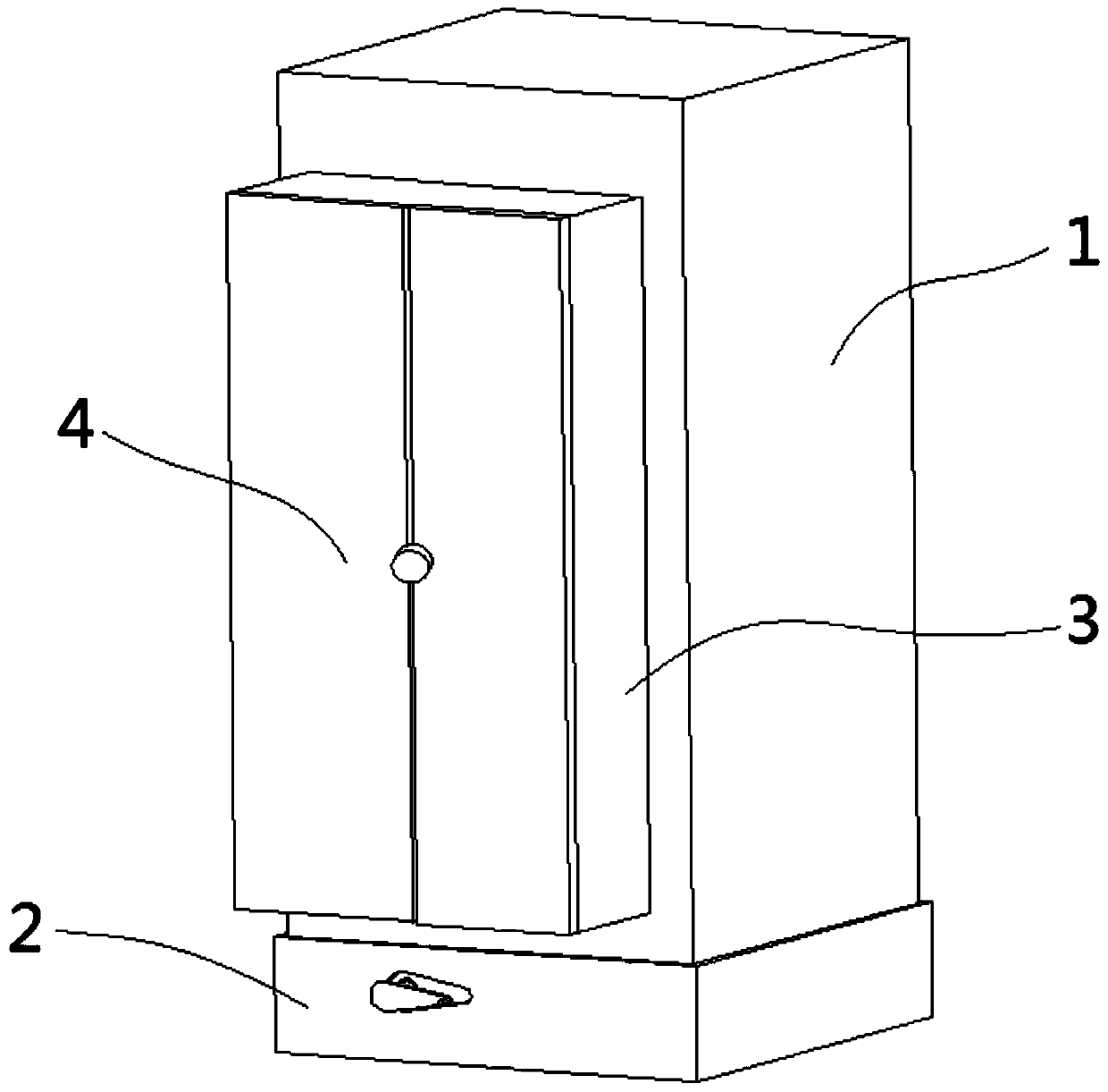
[0045] Electrical screen cabinets, such as figure 1 As shown, it includes a cuboid-shaped cabinet body 1 with a built-in cavity, a bracket 11 is placed in the cavity of the cabinet body 1, and required components are installed on the bracket 11 .

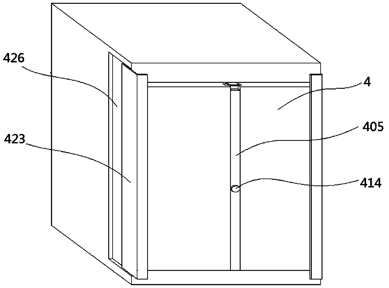
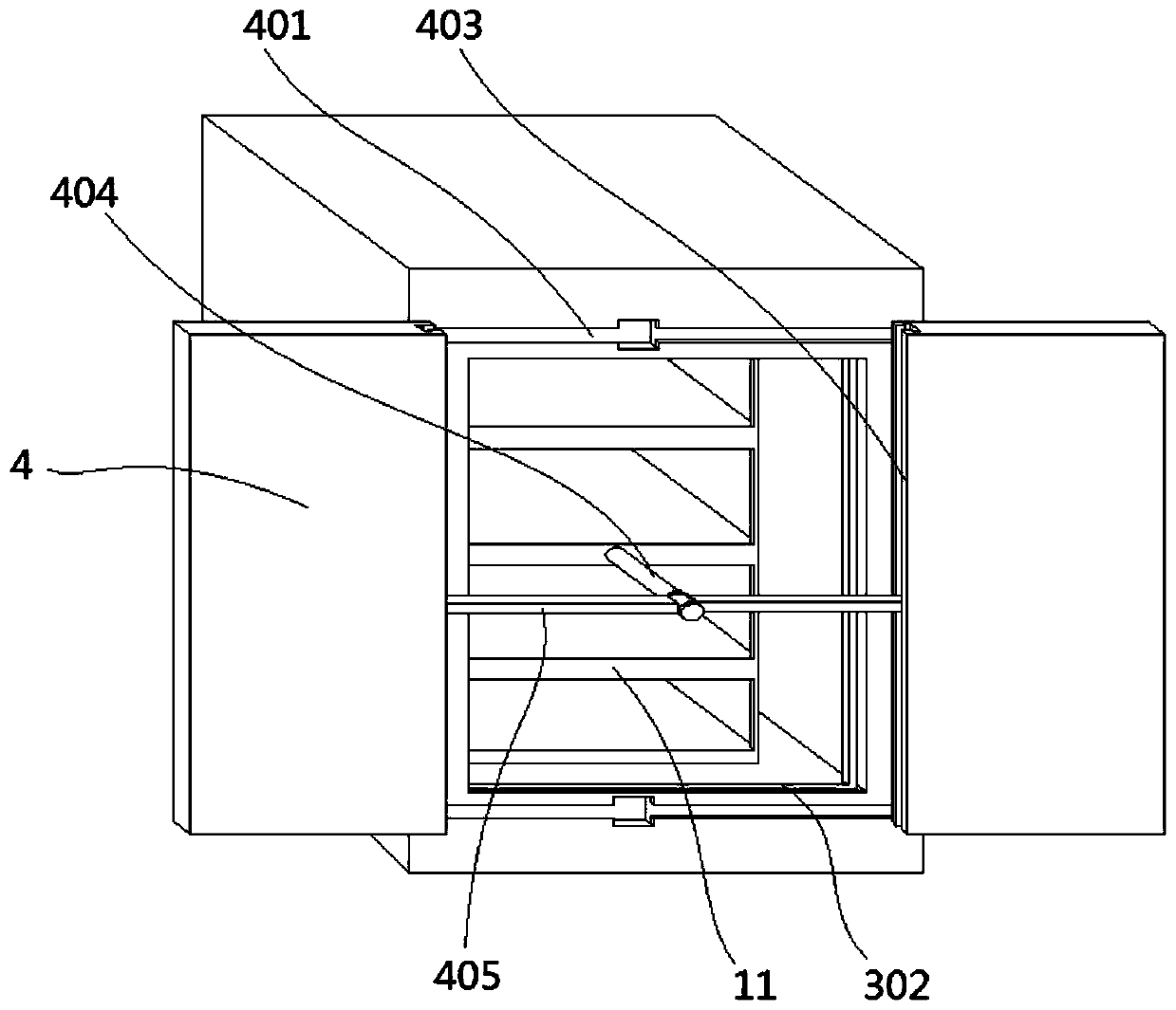
[0046] The bottom of the cabinet 1 is provided with a base 2, and the cabinet 1 is fixed on the base 2. The cabinet 1 is provided with a volume expansion body 3 that can protrude from the front end of the cabinet 1 and make a linear reciprocating motion along the width direction of the cabinet 1. The volume The extension body 3 is a rectangular frame body including four side panels and a door body 4 is provided on the front surface. The cavity of body 1 forms a cavity. After opening the door body 4, the components in the cabinet body 1 and the volume expansion body 3 can be observed, and then the internal components can be installed, repaired, replaced and other operations.

[0047] The base 2 is a rectangular frame structure with ...


PUM


Abstract

The invention relates to electrical equipment. The invention discloses an electrical screen cabinet. The cabinet comprises a cabinet body, a volume expansion body which can extend out of the front endface of the cabinet body and does linear reciprocating motion in the width direction of the cabinet body is arranged in the cabinet body. The volume expansion body is a rectangular frame body comprising four side plates, two door bodies are arranged on the front end face of the volume expansion body, the two door bodies are oppositely arranged and can do linear reciprocating motion in the opposite directions, and the volume expansion body further comprises a rod assembly used for opening the two door bodies. According to the invention, the telescopic volume expansion body is arranged in the cabinet body. Therefore, the internal volume of the whole cabinet body is changed, the application range of equipment is enlarged, the equipment can be reasonably arranged, the requirements are fully met, the door body is designed to be pushed and pulled towards the two sides, the door body is pushed and pulled through a rod assembly with a rotating rod and a rotary knob, and operation is very convenient.

Description

technical field [0001] The invention relates to electrical equipment, in particular to an electrical screen cabinet. Background technique [0002] The electrical screen cabinet is a cabinet made of steel to protect the normal operation of components. It is widely used in chemical industry, environmental protection industry, power system, metallurgical system, industry, nuclear power industry, fire safety monitoring, transportation industry, etc. wait. [0003] The general structure of the electrical screen cabinet is composed of an external shell and an internal bracket. The internal bracket is used to place various components, and is generally in the shape of a cuboid. Due to the large number of components inside, the overall volume is large, and the working space is relatively large. This type of electrical cabinet can fully meet the needs of factories or workshops, but for some factories or workshops with small working space, some larger electrical cabinets are difficult...

Claims


Application Information

Patent Timeline
Patent Type & Authority Patents(China)
IPC IPC(8): H02B1/30
CPCH02B1/30H02B1/303
Inventor 任为民谢长山
Owner 任为民
Why Eureka
Try Eureka