Power cable protection sleeve with waterproof structure
A technology of power cables and waterproof structures, applied in the direction of electrical components, etc., can solve problems such as inability to effectively fix cables, unstable structures, poor heat dissipation, etc., and achieve the effects of convenient installation, ensuring stability, and reducing volume
- Summary
- Abstract
- Description
- Claims
- Application Information
AI Technical Summary
Problems solved by technology
Method used
Image
Examples
Embodiment 1
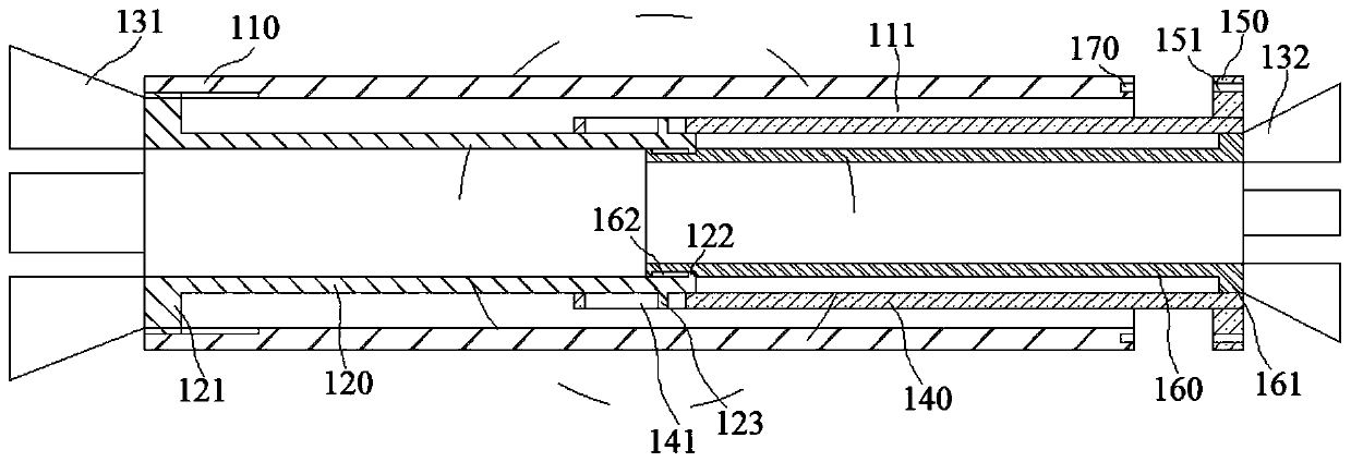
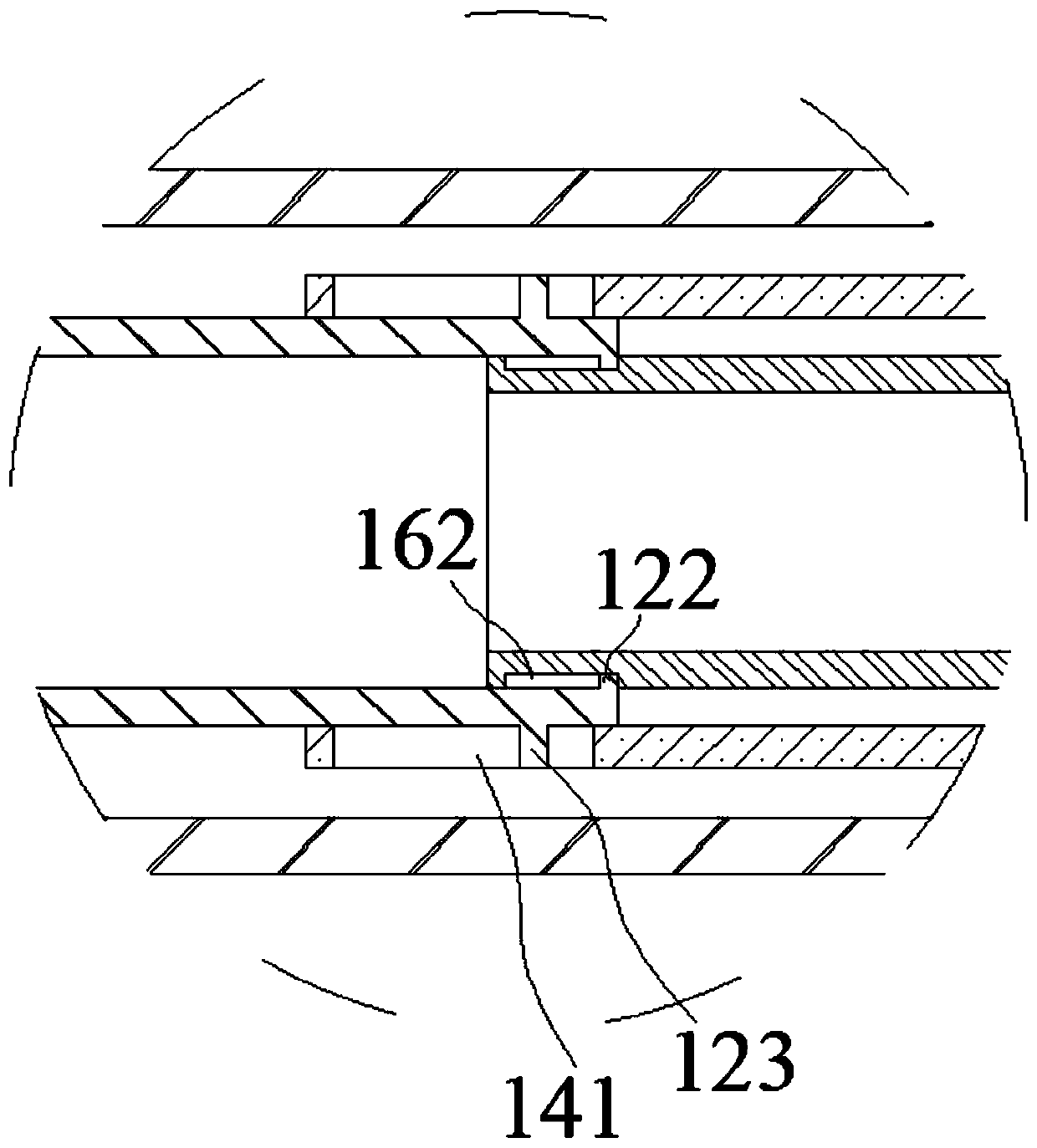
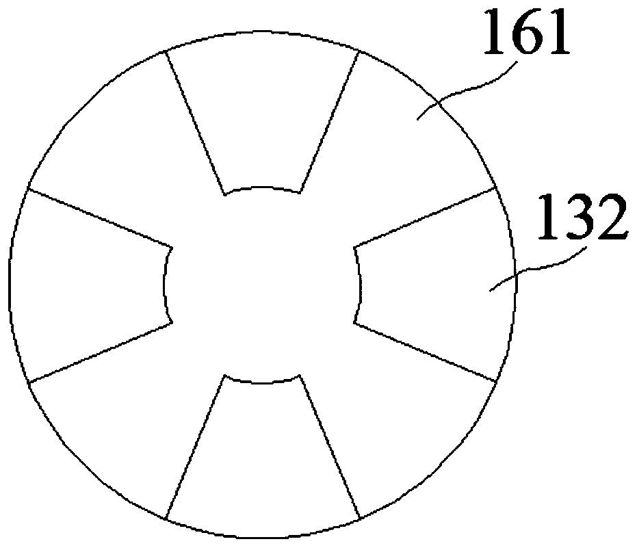
[0105] Such as figure 1 , figure 2 with image 3 As shown, the present embodiment provides an electric pipeline protection tube with a clamping structure, which includes a tube body 110, a lumen 111 is arranged in the tube body 110, a first movable tube 120 is arranged in the lumen 111, and a first movable tube 120 is arranged in the first The left end of the movable tube 120 is provided with a first protruding ring 121, and the first protruding ring 121 is threadedly connected to the wall of the lumen 111; The second movable tube 140 and the third movable tube 160 are located in the inner cavity of the second movable tube 140; the right end of the second movable tube 140 is provided with a retaining ring 150, and the right end of the third movable tube 160 is provided with a second protruding ring 161, and the second protruding ring 161 is provided at the right end of the second protruding tube. The ring 161 abuts against the inner wall of the right end of the second movab...
Embodiment 2
[0126] Such as Figure 4 with Figure 5 As shown, the present embodiment provides a protective device for electrical pipelines, which includes a tube body 110, a tube cavity 111 is provided in the tube body 110, a water inlet hole 210 is provided at the top of the tube body 110, and the top of the tube cavity 111 is A first water collection tank 220 is provided, and a first water collection chamber 221 is provided in the first water collection tank 220, and the first water collection chamber 221 communicates with the water inlet hole 210; the bottom of the lumen 111 is provided with a second water collection tank 230 , the second water collection tank 230 is provided with a second water collection chamber 231 , and the second water collection chamber 231 communicates with the first water collection chamber 221 through a plurality of connecting pipes 240 .
[0127] The setting of the water inlet hole 210 on the top of the pipe body 110 can conveniently collect the water above ...
Embodiment 3
[0141] Such as Figure 8 with Figure 9 As shown, this embodiment provides a power cable wall penetration device with better stability, which includes a tube body 110, a lumen 111 is provided inside the tube body 110, and a fixing tube 310 is threaded on the outside of the tube body 110. The outside of the fixed pipe 310 is threaded with more than two collars 320, and the outer surface of the fixed pipe 310 and the collar 320 are arranged in the cement layer of the through hole of the wall; the outer side of the pipe body 110 is also threaded with two rings 330, the two circular rings 330 are located at both ends of the fixed tube 310, and the inner side of the circular rings 330 is provided with a housing chamber 331, and the wall of the housing chamber 331 can be threaded on the outer side of the fixed tube 310.
[0142] The threaded connection between the pipe body 110 and the fixed pipe 310 enables the pipe body 110 to be disassembled from the fixed pipe 310. When the fix...
PUM
 Abstract
Description
Claims
Application Information
 - R&D
- Intellectual Property
- Life Sciences
- Materials
- Tech Scout
- Unparalleled Data Quality
- Higher Quality Content
- 60% Fewer Hallucinations
Browse by: Latest US Patents, China's latest patents, Technical Efficacy Thesaurus, Application Domain, Technology Topic, Popular Technical Reports.
© 2025 PatSnap. All rights reserved.Legal|Privacy policy|Modern Slavery Act Transparency Statement|Sitemap|About US| Contact US: help@patsnap.com


