
Terminal and control method and device thereof

A terminal and sub-area technology, applied in the direction of telephone structure, telephone communication, electrical components, etc., can solve the problem of small display image area, and achieve the effect of expanding the area and avoiding interference.

Active Publication Date: 2019-04-05
GUANGDONG OPPO MOBILE TELECOMM CORP LTD
View PDF5 Cites 2 Cited by
  • Summary
  • Abstract
  • Description
  • Claims
  • Application Information

AI Technical Summary

Problems solved by technology

[0002] Terminals, such as mobile phones, tablet computers, laptops, etc. are usually equipped with display screens to display images, and other functional devices, such as receivers, light sensors, proximity sensors, cameras, TOF depth cameras, etc., for the normal operation of these functional devices , functional devices are usually set in a space that is staggered from the display screen. When the front size of the terminal remains the same, setting functional devices will result in a smaller display image area of ​​the terminal

Method used


Image

  • Terminal and control method and device thereof
  • Terminal and control method and device thereof
  • Terminal and control method and device thereof

Examples


Embodiment Construction

[0026] Embodiments of the present application will be further described below in conjunction with the accompanying drawings. The same or similar reference numerals in the drawings represent the same or similar elements or elements having the same or similar functions throughout.

[0027] In addition, the embodiments of the present application described below in conjunction with the accompanying drawings are exemplary, and are only used to explain the embodiments of the present application, and should not be construed as limiting the present application.

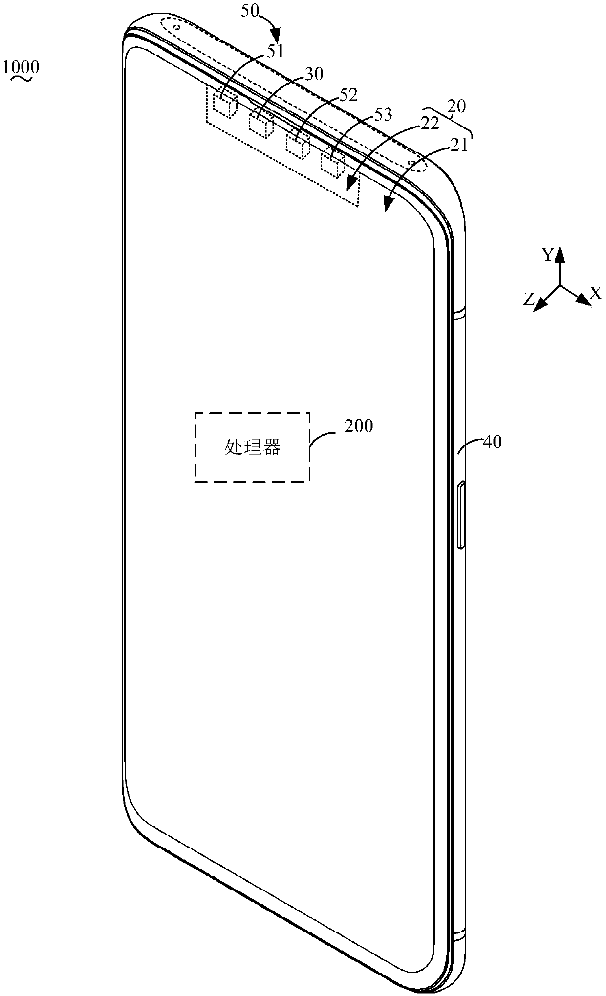
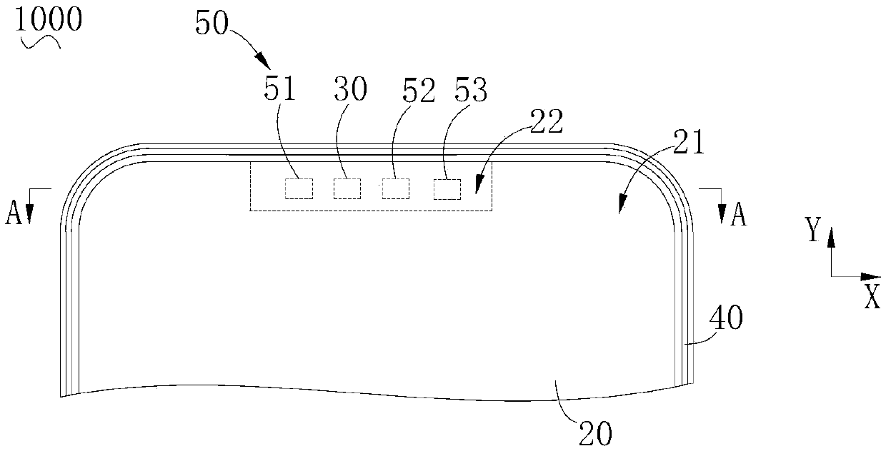
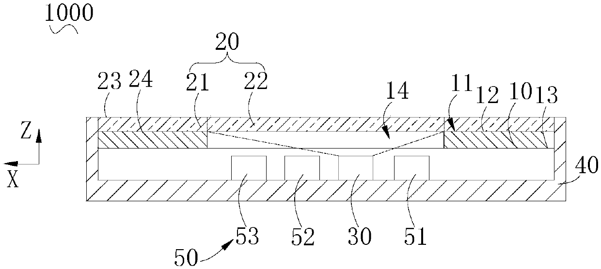
[0028] Please also refer to Figure 1 to Figure 3 , the terminal 1000 in the embodiment of the present application includes a display screen 10 , a cover plate 20 and a projection module 30 . The display screen 10 is formed with a display area 11 for displaying a first image. The cover plate 20 is formed with a first sub-region 21 and a second sub-region 22 , and the first sub-region 21 corresponds to the display area 11 . ...


PUM


Abstract

The invention provides a terminal and a control method and device thereof. The terminal comprises a display screen, a cover plate, a projection module and a flight time assembly. A display screen forms a display area for displaying a first image; the cover plate forms first and second subareas, and the first subarea corresponds to the display area. The projection module projects a second image tothe second subarea, and the display screen, the projection module and the flight time assembly are positioned in the same side of the cover plate. The flight time assembly is arranged corresponding tothe second subarea, and comprises a light emitter and a light receiver, laser emitted by the laser emitter penetrates the second subarea to reach a target object, and the light receiver receives thelaser which is reflected by the target object and penetrates the second subarea. The projection module does not shield the first image displayed by the display screen, and can project a second image,and the area of the display image of the terminal is increased; and the fight time assembly is avoided from interference of the display screen during laser emission and reception.

Description

technical field [0001] The present application relates to the field of consumer electronics, and more specifically, to a terminal, a terminal control method, and a terminal control device. Background technique [0002] Terminals, such as mobile phones, tablet computers, laptops, etc. are usually equipped with display screens to display images, and other functional devices, such as receivers, light sensors, proximity sensors, cameras, TOF depth cameras, etc., for the normal operation of these functional devices , the functional devices are usually arranged in a space staggered from the display screen. When the front size of the terminal remains unchanged, setting the functional devices will result in a smaller display image area of ​​the terminal. Contents of the invention [0003] Embodiments of the present application provide a terminal, a terminal control method, and a terminal control device. [0004] The terminal in the embodiment of the present application includes a...

Claims


Application Information

Patent Timeline
Patent Type & Authority Applications(China)
IPC IPC(8): H04M1/02
CPCH04M1/026H04M1/0266H04M1/0272H04M2250/54
Inventor 杨鑫
Owner GUANGDONG OPPO MOBILE TELECOMM CORP LTD
Learn More