Disinfection device and disinfection cabinet employing same

A disinfection device and cabinet technology, applied in the field of disinfection cabinets and disinfection devices, can solve the problems of limited disinfection range, inconvenient use, uneven distribution of ultraviolet rays, etc., achieve good disinfection effect, uniform distribution, and improve disinfection effect

Pending Publication Date: 2019-04-09
NINGBO FOTILE KITCHEN WARE CO LTD
View PDF1 Cites 5 Cited by
  • Summary
  • Abstract
  • Description
  • Claims
  • Application Information

AI Technical Summary

Problems solved by technology

The disinfection cabinet with the above structure makes the utensils to be sterilized close to the ultraviolet rays and achieves the disinfection effect by rotating the bowl rack. However, this cannot fundamentally solve the problem, because the position of the ultraviolet lamp tube is fixed, and the disinfection range it can cover is limited. Moreover, due to the uneven distribution of ultraviolet rays in the disinfection range, the disinfection effect of each position is also different. Turning the bowl rack can only make the utensils on the bowl racks sterilize after entering the disinfection range, but the utensils in the corners of the disinfection cabinet still cannot achieve the disinfection effect. , not only seriously affected the disinfection effect, but also caused the space in the disinfection cabinet to not be effectively utilized, making it inconvenient to use

Method used


Image

  • Disinfection device and disinfection cabinet employing same
  • Disinfection device and disinfection cabinet employing same
  • Disinfection device and disinfection cabinet employing same

Examples


Embodiment Construction

[0033] The present invention will be further described in detail below in conjunction with the accompanying drawings and embodiments.

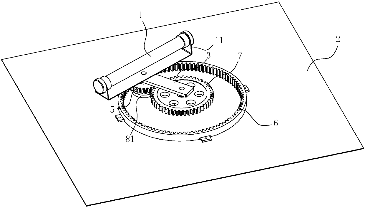
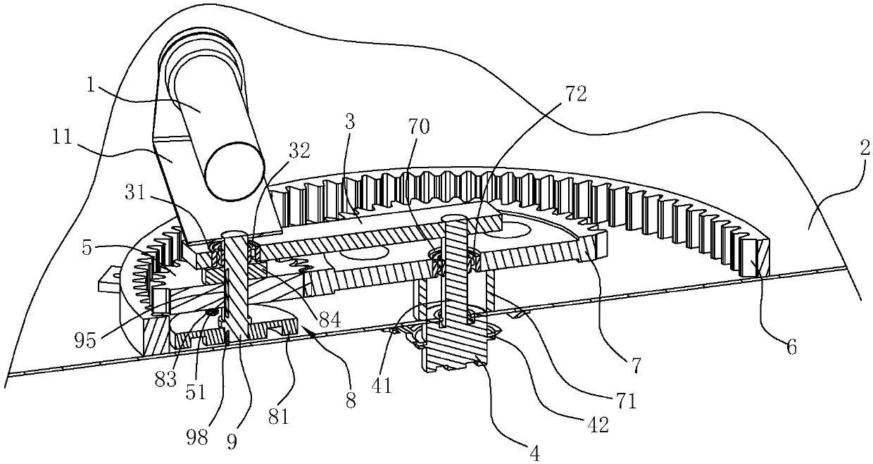
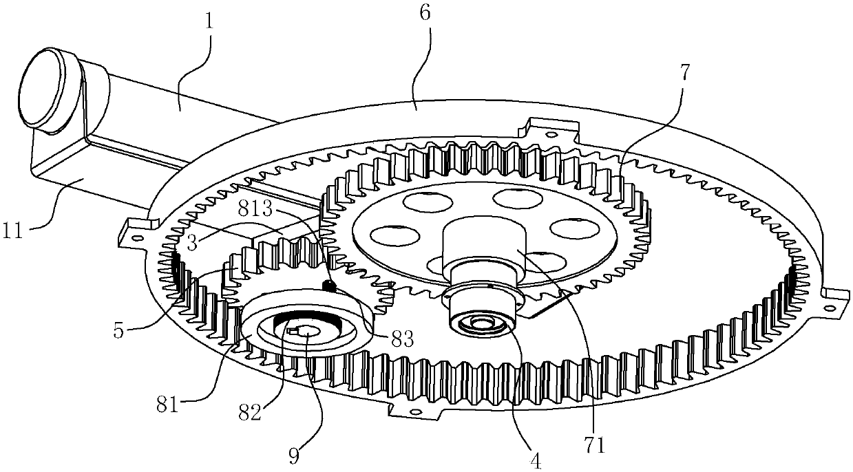
[0034] Such as Figure 1~6 As shown, the disinfection device of the present embodiment includes an ultraviolet lamp 1, a panel 2, a connecting rod 3, a driving member 4, a first gear 5, a ring gear 6, a second gear 7 and a clutch mechanism 8, and the connecting rod 3 can rotate Located on the first side of the panel 2; the driving member 4 is connected to the first end of the connecting rod 3 and used to drive the connecting rod 3 to rotate with the first end as the center; the first gear 5 is rotatably arranged on the connecting rod 3 On the second end; the ring gear 6 is arranged on the first side of the panel, the teeth of the ring gear 6 are located on the inner surface and can be meshed with the first gear 5; the second gear 7 is arranged on the first side of the panel 2 And can be meshed with the first gear 5; the clutch mechanism 8 is ...


PUM


Abstract

The invention relates to a disinfection device and a disinfection cabinet employing the disinfection device. The disinfection device comprises an ultrasonic lamp tube, a surface plate, a connecting rod, a driving part, a first gear, a gear ring, a second gear and a clutch mechanism. Due to the adoption of the connecting rod, the driving part, the first gear, the gear ring, the second gear and theclutch mechanism, the ultrasonic lamp tube is rotationally arranged on the surface plate, when being operated, the ultrasonic lamp tube is driven by the connecting rod to revolute around a first end of the connecting rod, meanwhile, the ultrasonic lamp tube is rotated along with the first gear, in addition, when the first gear is meshed with the gear ring and the second gear respectively, the first gear is in opposite revolution directions, then the revolution direction of the ultrasonic lamp tube can be changed on the basis that the rotation direction of a motor is not changed, ultraviolet rays emitted from the ultrasonic lamp tube can be sufficiently scattered, the ultraviolet rays are uniformly distributed in the disinfection cabinet, and a good disinfection effect can be achieved for the components to be disinfected in different positions; by adopting the disinfection device provided by the invention, controllable adjustment on a double-ultraviolet lamp tube disinfection range andultraviolet ray uniformity can be achieved, and the disinfection effect can be improved.

Description

technical field [0001] The invention relates to a disinfection device and a disinfection cabinet using the disinfection device. Background technique [0002] Most of the disinfection cabinets currently on the market are high temperature or ozone disinfection. Occasionally, ultraviolet disinfection cabinets are combined with high temperature or ozone, and there are few independent ultraviolet disinfection cabinets. The reason is that the disinfection range of ultraviolet light disinfection in the cabinet is limited. It is easy to cause incomplete disinfection and has certain defects. [0003] In order to solve the above problems, the Chinese invention patent application "rotary ultraviolet disinfection cabinet" (application number: CN201010512726.5) with the application publication number CN102451478A discloses a structure, which includes a disinfection room, an electric control room, a motor, and a rectifier. A dish rack assembly and an ultraviolet disinfection lamp tube ar...

Claims


Application Information

Patent Timeline
Patent Type & Authority Applications(China)
IPC IPC(8): A61L2/10A61L2/26
CPCA61L2/10A61L2/26
Inventor 张文龙王军元刘小祥陈龙灿茅忠群诸永定
Owner NINGBO FOTILE KITCHEN WARE CO LTD
Why Eureka
Try Eureka