Safety clamp and cargo carrying platform

A cargo platform and safety gear technology, applied in the direction of lifting devices, etc., can solve the problems of safety and hidden dangers in the cargo platform

Pending Publication Date: 2019-04-09
湖北科德智能装备有限公司 +2
View PDF0 Cites 2 Cited by
  • Summary
  • Abstract
  • Description
  • Claims
  • Application Information

AI Technical Summary

Problems solved by technology

[0004] In order to solve the above-mentioned problems in the prior art, the present invention provides a safety gear that improves t

Method used


Image

  • Safety clamp and cargo carrying platform
  • Safety clamp and cargo carrying platform
  • Safety clamp and cargo carrying platform

Examples


Embodiment 1

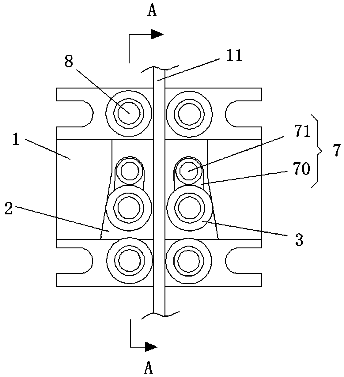
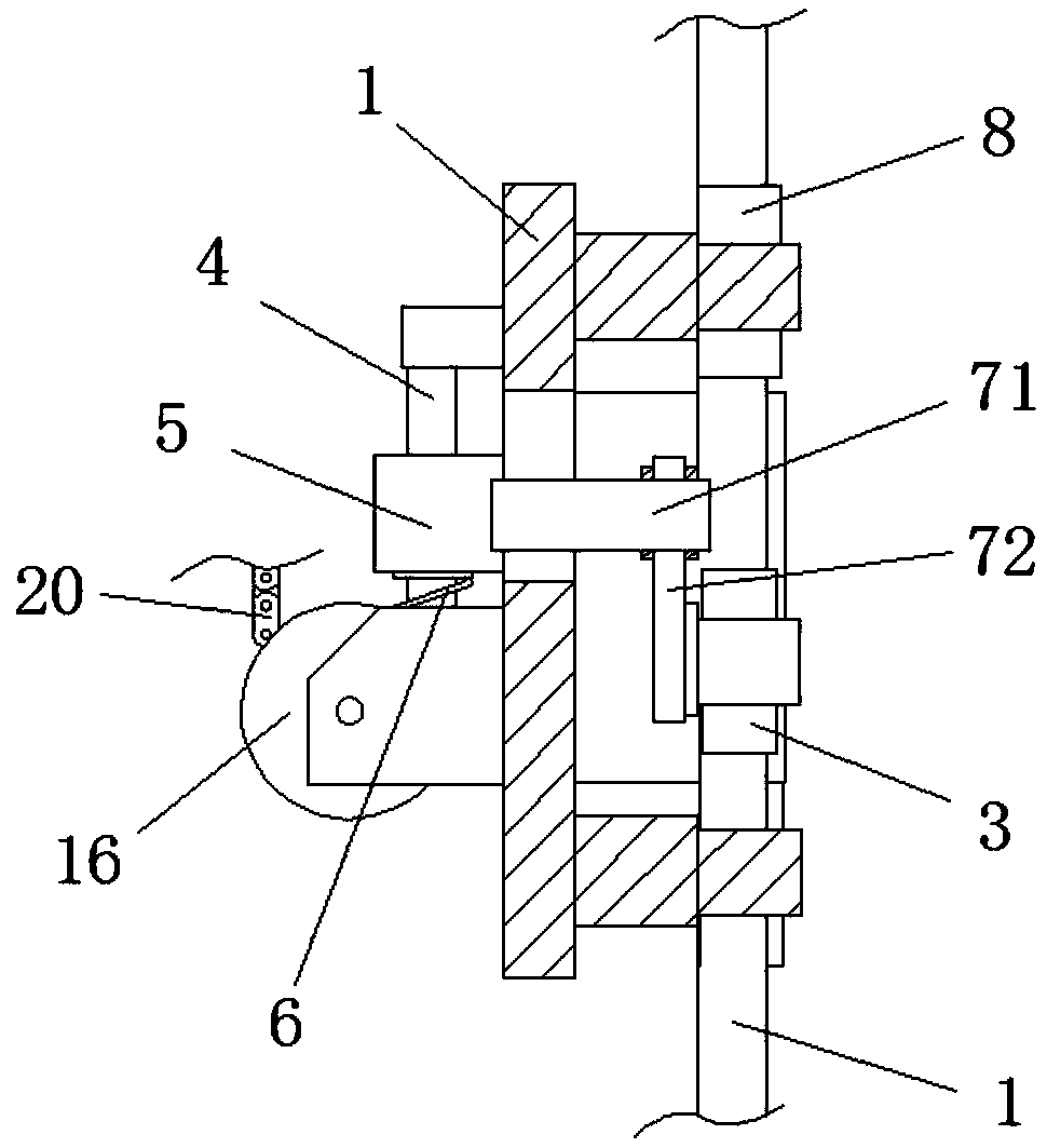
[0032] a safety gear such as figure 1 and figure 2 As shown, it includes a clamp seat plate 1, a trapezoidal guide groove 2 is provided on the clamp seat plate 1, and two brake wheels 3 rolling along the hypotenuse of the guide groove 2 are arranged in the guide groove 2, and the clamp seat plate 1 Also vertically provided with a guide rod 4 and a slide plate 5 moving up and down along the guide rod 4, the two ends of the slide plate 5 are respectively movably connected with the two brake wheels 3, and the guide rod 4 is also provided with guide grooves for guiding the slide plate 5 to The elastic part 6 that the narrow end of 2 promotes.

[0033] Through a kind of safety gear with the above structure, when it is installed on the cargo platform body 9, the guide rail 11 of the cargo platform is located between the two brake wheels 3, and the two brake wheels 3 are in the guide groove 2 The wide end of the brake wheel 3 makes the distance between the two brake wheels 3 great...

Embodiment 2

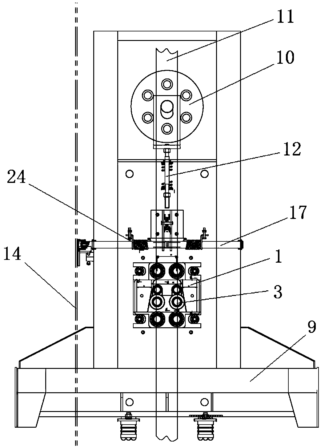
[0041] The present invention also provides a loading platform, such as Figure 1 to Figure 5As shown, the cargo platform includes a cargo platform body 9 and a speed limiting device. The cargo platform body 9 is provided with a first fixed pulley 10 that is convenient for hoisting by a traction rope. The cargo platform also includes the safety gear in the first embodiment. Clamp, the guide rail 11 of the cargo platform body 9 is located between the two brake wheels 3, and the cargo platform body 9 is also provided with a pull rod 12 that pulls the first fixed pulley 10 downward;

[0042] The speed limiting device includes a speed limiter 13, a speed limiter rope 14 and a reversing wheel 15, the speed limiter rope 14 is wrapped around the speed limiter 13 and the reversing wheel 15, the safety gear is provided with a second fixed pulley 16, and the cargo platform The body 9 is provided with a trigger device and a trigger lever 17 for triggering the safety gear. The trigger devi...


PUM


Abstract

The invention belongs to the technical field of safety auxiliary equipment, and particularly relates to a safety clamp and a cargo carrying platform. The safety clamp comprises a clamp seat plate, wherein the clamp seat plate is provided with a trapezoidal guide groove; two brake wheels rolling along the bevel edge of the guide groove are arranged in the guide groove; a guiding rod is vertically arranged on the clamp seat plate; a sliding plate moving along the guiding rod top and down is also arranged on the clamp seat plate; two ends of the sliding plate are movably connected with the two brake wheels; and an elastic member for pushing the sliding plate toward the narrow end of the guide groove is arranged on the guiding rod. Through the arrangement of the safety clamp on the cargo carrying platform, the sliding plate is guided by the elastic member to move toward the narrow end of the guide groove when the descending of the cargo carrying platform is too fast or the breaking of a hauling cable starts the safety clamp, and then constrained by the guide groove, the two brake wheels move close to each other for holding guide sliding rails under the action of the inclined surface ofthe guide groove for achieving the effect of braking so that the safety of the cargo carrying platform can be improved.

Description

technical field [0001] The invention belongs to the technical field of safety auxiliary equipment, and in particular relates to a safety gear and a cargo platform. Background technique [0002] The automatic storage and retrieval of goods in the high-rise three-dimensional warehouse is completed by the combination of the horizontal movement of the stacker, the vertical lifting movement of the loading platform and the forward and backward movement of the cargo fork. Among them, the loading platform is an important part of the stacker. Mainly used for placing and moving goods. [0003] At present, the existing cargo platforms used for stackers are not equipped with special safety protection devices. , the high-speed running cargo platform cannot be stopped in time, and there is a certain potential safety hazard; therefore, it is a technical problem to be solved urgently by those skilled in the art to provide a safety gear and a cargo platform with high safety. Contents of t...

Claims


Application Information

Patent Timeline
IPC IPC(8): B66F9/075
CPCB66F9/07504B66F9/07509
Inventor 汪博韬汪胜志李光涛李田野
Owner 湖北科德智能装备有限公司
Why Eureka
Try Eureka