
Fixing device for undervoltage protector

A technology of fixing devices and protectors, applied in substation/switch layout details, electrical components, etc., can solve the problems of wire falling off, falling off, cumbersome installation and disassembly, etc., and achieve the effects of improving work efficiency, stable and reliable installation, and saving time

Active Publication Date: 2022-04-01
广东求精电气有限公司
View PDF9 Cites 0 Cited by
  • Summary
  • Abstract
  • Description
  • Claims
  • Application Information

AI Technical Summary

Problems solved by technology

[0002] The existing box fixing devices are generally snapped on the guide rails, and the guide rails are provided in the box, and are snapped on the guide rails with an integrated device. However, this kind of fixing device cannot be used in some specific positions. , and the fixing device also has the situation that the clamping is not secure
[0003] Due to different site environments, sometimes it is necessary to use different types of undervoltage protectors, and sometimes they need to be used in combination. Since there is no fixation between adjacent undervoltage protectors, it is very difficult to It is easy to cause the overvoltage protector to slide or fall off, making the undervoltage protector deviate from the original position
In addition, it is easy to cause deformation of the wire of the undervoltage protector, and even cause the wire to fall off, and the adjacent undervoltage protector is not fixed, and the installation and removal are very cumbersome

Method used


Image

  • Fixing device for undervoltage protector
  • Fixing device for undervoltage protector
  • Fixing device for undervoltage protector

Examples


Embodiment Construction

[0026] The present invention will be further described below in combination with specific embodiments. Wherein, the accompanying drawings are only for illustrative purposes, showing only schematic diagrams, rather than physical drawings, and should not be construed as limitations on this patent; in order to better illustrate the embodiments of the present invention, some parts of the accompanying drawings will be omitted, Enlargement or reduction does not represent the size of the actual product; for those skilled in the art, it is understandable that certain known structures and their descriptions in the drawings may be omitted.

[0027] In the drawings of the embodiments of the present invention, the same or similar symbols correspond to the same or similar components; The orientation or positional relationship indicated by etc. is based on the orientation or positional relationship shown in the drawings, which is only for the convenience of describing the present invention ...


PUM


Abstract

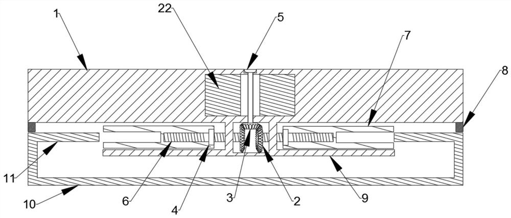
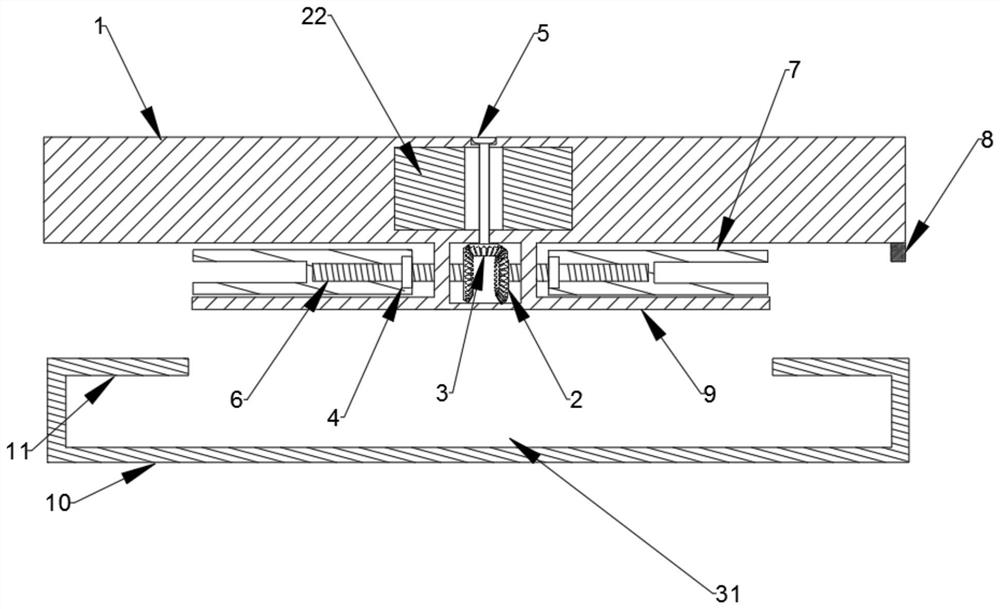
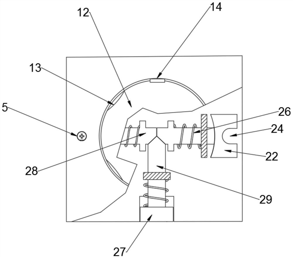
The invention provides a fixing device for an undervoltage protector, which includes a card base body and a guide rail. The card base body is provided with a clamping mechanism. There are several through holes on the body, and each through hole is provided with a pin rod and communicates with the gear chamber. The gear chamber is respectively provided with a first bevel gear and two second bevel gears. One end of the pin rod is rotatably connected to the card holder body The top of the top, the other end is fixedly connected to the first bevel gear, and the two second bevel gears are symmetrically meshed on both sides of the first bevel gear, and the axis of the first bevel gear and the second bevel gear The axis of the shaft is vertical, and the two clamping cavities are symmetrically arranged on both sides of the gear cavity, facing away from each other. Each second bevel gear is vertically fixedly connected to one end of the threaded rod, and the other end of the threaded rod extends into the clamping cavity and connects to the resisting cavity in the cavity. pick up. The fixing device of the invention is simple in structure, stable and reliable, greatly saves time, and improves clamping efficiency.

Description

technical field [0001] The invention relates to the field of electrical equipment accessories, in particular to a fixing device for an undervoltage protector. Background technique [0002] The existing box fixing devices are generally snapped on the guide rails, and the guide rails are provided in the box, and are snapped on the guide rails with an integrated device. However, this kind of fixing device cannot be used in some specific positions. , and the fixing device also has unreliable clamping. [0003] Due to different site environments, sometimes it is necessary to use different types of undervoltage protectors, and sometimes they need to be used in combination. Since there is no fixation between adjacent undervoltage protectors, it is very difficult to It is easy to cause the overvoltage and undervoltage protector to slide or fall off, causing the undervoltage protector to deviate from its original position. In addition, it is easy to cause deformation of the wire of...

Claims


Application Information

Patent Timeline
Patent Type & Authority Patents(China)
IPC IPC(8): H02B1/052
CPCH02B1/052
Inventor 赵成雷陈正茂张传荣
Owner 广东求精电气有限公司
Learn More