

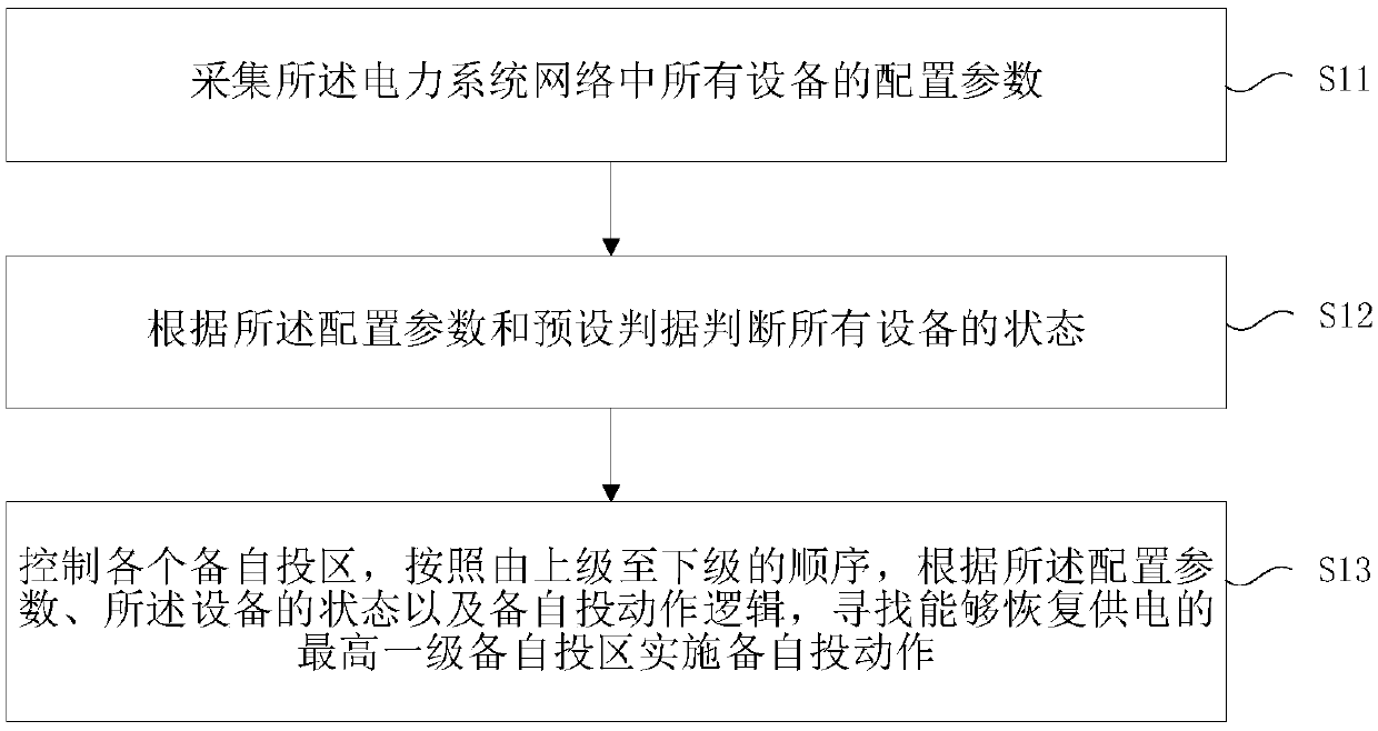
Reserved auto-switch-on method requiring free setting of fixed value based on trend direction partition topology
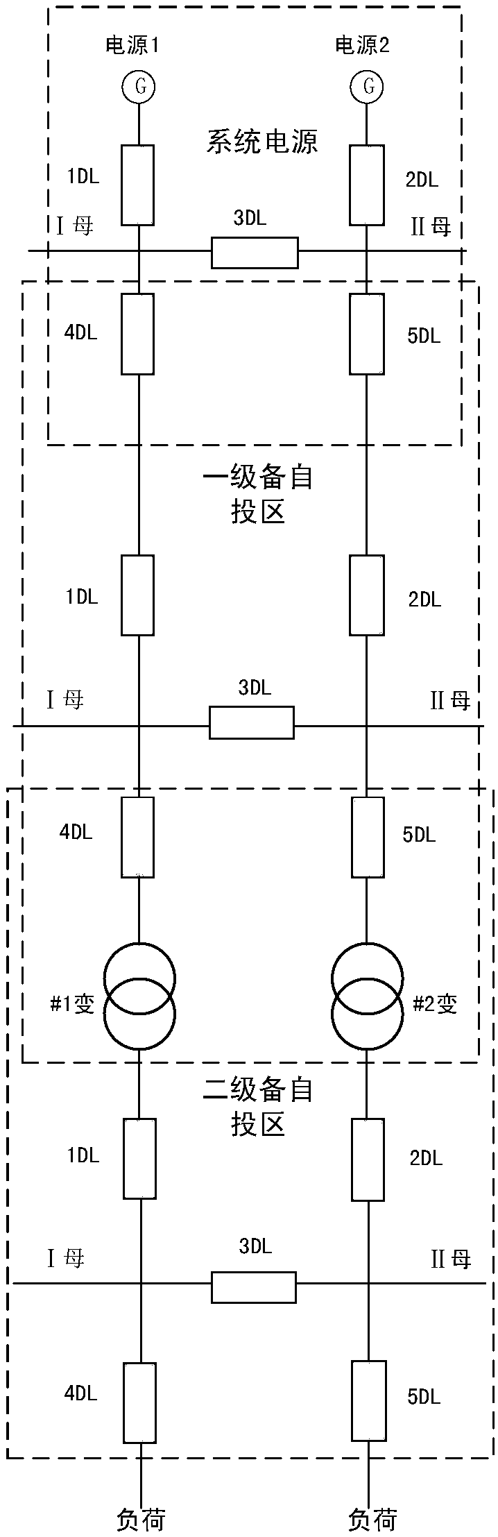
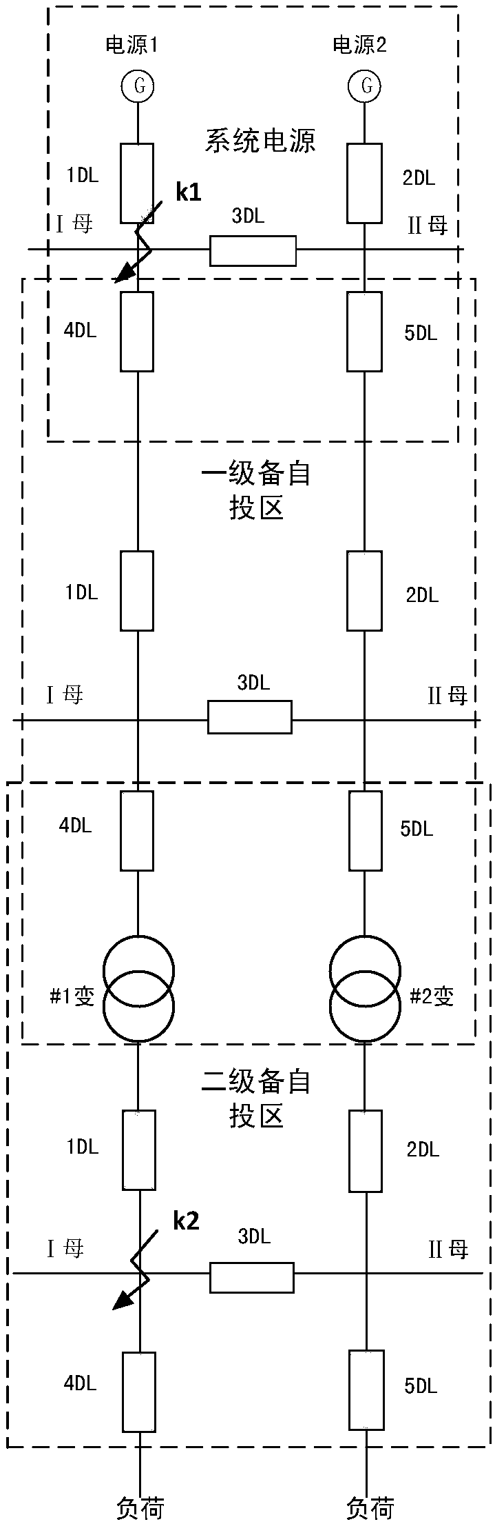
A technology of power flow direction and self-switching, which is applied to AC network circuits, AC networks with the same frequency from different sources, electrical components, etc. It is impossible to realize the self-switching of multi-segment busbars and increase the difficulty of debugging the equipment for self-switching, so as to reduce the commissioning period, ensure the power supply, and reduce the workload.
- Summary
- Abstract
- Description
- Claims
- Application Information
AI Technical Summary
Problems solved by technology
Method used
Image

Examples
Embodiment Construction
[0040] Various exemplary embodiments, features, and aspects of the present disclosure will be described in detail below with reference to the accompanying drawings. The same reference numbers in the figures indicate functionally identical or similar elements. While various aspects of the embodiments are shown in drawings, the drawings are not necessarily drawn to scale unless specifically indicated.
[0041] The word "exemplary" is used exclusively herein to mean "serving as an example, embodiment, or illustration." Any embodiment described herein as "exemplary" is not necessarily to be construed as superior or better than other embodiments.
[0042] In addition, in order to better illustrate the present disclosure, numerous specific details are given in the following specific implementation manners. It will be understood by those skilled in the art that the present disclosure may be practiced without some of the specific details. In some instances, methods, means, componen...
PUM
 Abstract
Description
Claims
Application Information