
Oil-based ink stirring device

A stirring device, oil-based ink technology, used in mixers with rotary stirring devices, mixer accessories, transportation and packaging, etc.

Active Publication Date: 2019-04-12
DONGGUAN POLYTECHNIC
View PDF7 Cites 2 Cited by
  • Summary
  • Abstract
  • Description
  • Claims
  • Application Information

AI Technical Summary

Problems solved by technology

[0004] The invention aims to solve the technical problem that the ink agitator will shake and throw the ink out

Method used


Image

  • Oil-based ink stirring device
  • Oil-based ink stirring device
  • Oil-based ink stirring device

Examples


Embodiment Construction

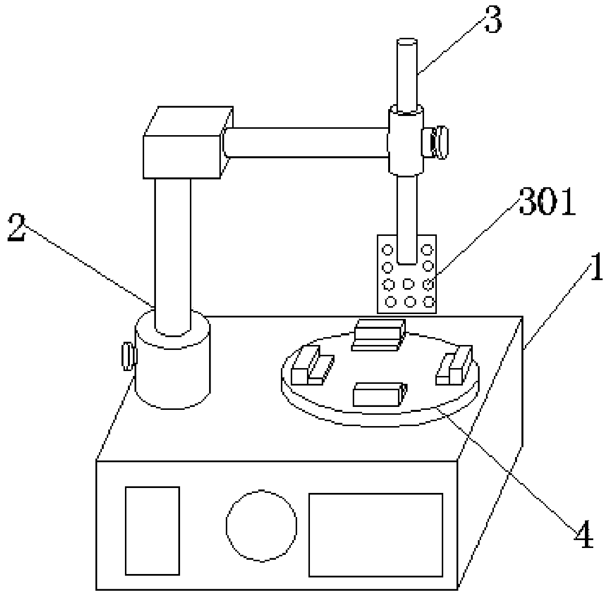
[0033] as attached figure 1 to attach Figure 9 Shown:

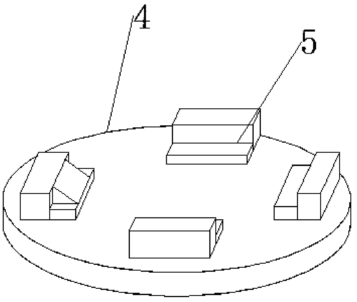
[0034] The present invention provides an oil-based ink stirring device, which includes a main body 1, a support rod 2, a stirring rod 3, a fixed base 4 and a fixed block 5. The top of the main body 1 is embedded with a support rod 2 near one side, and the top end of the support rod 2 is embedded A stirring rod 3 is provided, the bottom end of the stirring rod 3 is fixedly connected with a stirring blade 301, the top of the main body 1 is embedded with a fixed base 4, and the top of the fixed base 4 is embedded with a fixed block 5;

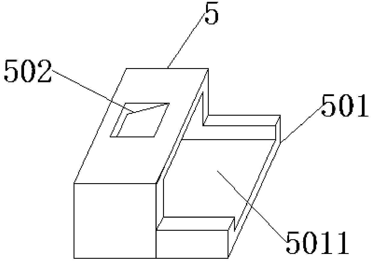
[0035] The fixed block 5 includes a placement plate 501, a socket 5011, a chute 502, a displacement block 503, a tooth mark 5031, a resisting block 504, a displacement shaft 505, a limit block 506, a slide rail 5061 and a limit rod 507, and the position plate 501 is fixed Connected to the bottom end of one side of the fixed block 5, the slot 5011 is opened in the middle of the top of the p...


PUM


Abstract

The invention provides an oil-based ink stirring device. The device comprises a device body, a supporting rod, a stirring rod, a fixed base and a fixing block, wherein the supporting rod is embedded in the side, close to the top end, of the device body, the stirring rod is embedded in the top end of the supporting rod, the bottom end of the stirring rod is fixedly connected with stirring blades, the fixed base is embedded in the top end of the device body, and the fixing block is embedded in the top end of the fixed base; the fixing block comprises a placing plate, an embedding groove, a sloping groove, a displacement block, a tooth mark, an abutting block, a displacement shaft, a limiting bock, a sliding rail and a limiting rod, the abutting block comprises a sucking disc, a retractable block, a lifting rod, a limiting tube and a displacement groove, and the displacement shaft comprises a rotating rod and a connecting rod. The oil-based ink stirring device has the advantages that thedisplacement block is arranged, and the displacement shaft is pushed through the inward retraction when the displacement block is subjected to the weight of sink, so that the abutting block stretchesout to fix an ink tank.

Description

technical field [0001] The invention relates to the technical field of ink processing, and more specifically relates to an ink stirring device. Background technique [0002] Ink refers to an important material used for color rendering in printing. It is an important writing material for existing characters and patterns, and the processing of ink is relatively cumbersome, and the stirring is the most basic and important part of it. For the part, the raw materials in it can be fully mixed together by stirring, so that the effect of the ink is better, and it also provides a good foundation for the later processing, but the existing stirring is done by putting the ink bucket Prevent it from being on the fixed base of the agitator, and then stir it through the rotation of the fixed base, but when stirring, it is only fixed by the fixed structure of the fixed base, and some ink barrels with higher heights will rotate. Sometimes, because the center of gravity cannot be effectively...

Claims


Application Information

Patent Timeline
Patent Type & Authority Applications(China)
IPC IPC(8): B01F7/18B01F15/00
CPCB01F27/11251B01F27/88B01F27/90B01F35/42B01F2101/35
Inventor 王旭红李小东张彦粉
Owner DONGGUAN POLYTECHNIC
Learn More