Helicopter coaxial double-cone rotor parallel manual device

A helicopter and coaxial technology, applied in the field of helicopters, can solve the problems of too many components, large bending moment of the rotor main shaft, complicated manufacturing, etc., and achieve the effects of simple control system, large rotor lift, and balanced anti-torque.

Active Publication Date: 2021-07-09
YANSHAN UNIV
View PDF13 Cites 0 Cited by
  • Summary
  • Abstract
  • Description
  • Claims
  • Application Information

AI Technical Summary

Problems solved by technology

[0004] Although the above-mentioned existing technologies have their own characteristics, the existing helicopter rotor technology still has the following inherent defects: the rotor heading control mechanism is complicated, there are too many components, and the transmission chain is long; the coaxial double-rotor heading control mechanism is more complicated.
Many components that rotate with the rotor main shaft are exposed outside the cabin, with a large area of ​​waste resistance and easy to be damaged and rotted; long blades are prone to flutter and loud noise; The load capacity is weak, not suitable for high-speed rotation; the fuselage swings synchronously with the rotor main shaft, the flight flexibility is poor, people are prone to dizziness, and it is difficult to lock the target; the bevel gear driving the coaxial dual rotor forward and reverse has high noise, large vibration, and complicated manufacturing , low load capacity, easy to wear

Method used


Image

  • Helicopter coaxial double-cone rotor parallel manual device
  • Helicopter coaxial double-cone rotor parallel manual device

Examples


Embodiment Construction

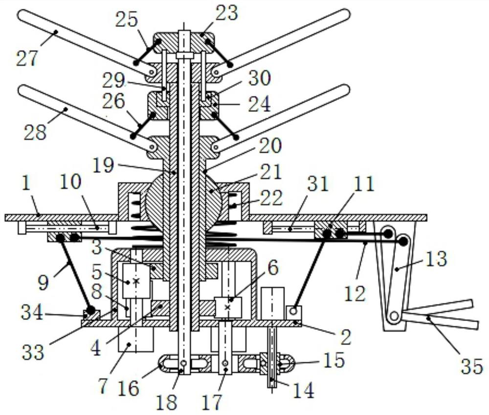
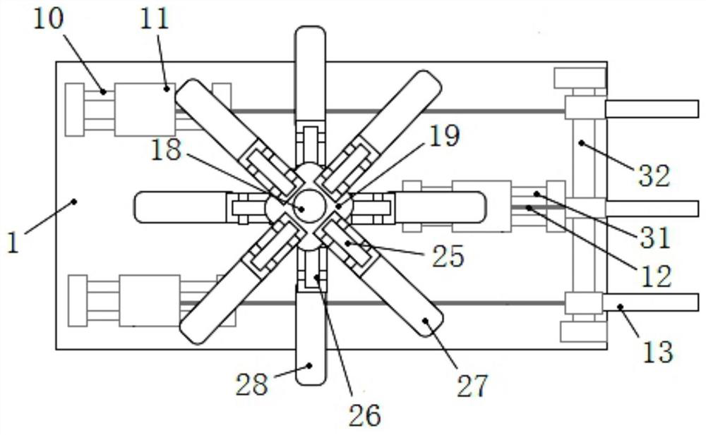
[0024] In order to more clearly illustrate the technical solutions in the embodiments of the present invention or the prior art, the following will briefly introduce the drawings that need to be used in the description of the embodiments or the prior art. Obviously, the accompanying drawings in the following description These are some embodiments of the present invention. Those skilled in the art can also obtain other drawings based on these drawings without creative work.

[0025] It should be noted that in the description of the present invention, it should be noted that the terms "upper", "lower", "top", "bottom", "one side", "another side", "left", " The orientation or positional relationship indicated by "right", etc. is based on the orientation or positional relationship shown in the drawings, and is only for the convenience of describing the present invention and simplifying the description, and does not mean that the device or element must have a specific orientation, b...


PUM


Abstract

The invention relates to a helicopter coaxial double-cone rotor parallel manual device. The device comprises a rotor wing group, a parallel mechanism, a forward and reverse rotation mechanism, a variable-cone mechanism and a spring; the rotor wing group comprises a core rod, an inner sleeve, an outer sleeve, a pull rod group, upper and lower paddle groups, upper and lower connecting rod groups, and upper and lower rings; the upper and lower paddle groups are rotationally connected with the upper ends of the inner and outer sleeves; the parallel mechanism is connected with the rotor wing group in parallel, and a hand-operated crank drives the rotor wing group to swing and stretch; the forward and reverse rotation mechanism drives a coaxial double-connecting-frame rotor wing to rotate forwardly and reversely through the inner and outer sleeves, upper and lower large gears, an idle gear and the upper and lower gears; the variable-cone mechanism changes the included angle between the blades and the axis of the rotor wing group through the core rod, the upper and lower rings and the upper and lower connecting rod groups, and changes the lift force and the flight speed. The device is simple and light, can change the flight direction, speed and lift flight, and has the advantages of high navigational speed, large rotor lift force, balanced reaction torque, simple structure, short fuselage, centered gravity center, symmetrical aerodynamic force, small rotation diameter, good stability and the like.

Description

technical field [0001] The invention relates to the technical field of helicopters, in particular to a helicopter coaxial double-cone rotor parallel manual device. Background technique [0002] Compared with traditional single-rotor helicopters, coaxial twin-rotor helicopters have many advantages and become an advanced model leading the development of helicopters in the world today. The rotor system is the most characteristic and most critical symbolic part of the helicopter. [0003] In recent years, patents on the rotor system include: Patent CN101961559B discloses a rotor support device for a model airplane helicopter, which uses a V-shaped bracket to absorb the shock waves generated by the helicopter, in order to reduce the vibration of the helicopter body. Patent CN101204992B discloses a helicopter coaxial dual-rotor speed differential device, in order to realize the yaw control of the coaxial dual-rotor helicopter. Patent CN101376433B discloses a helicopter rotor con...

Claims


Application Information

Patent Timeline
IPC IPC(8): B64C13/04B64C27/10B64C27/32B64C27/473
CPCB64C13/042B64C27/10B64C27/32B64C27/473Y02T50/40
Inventor 路懿常泽锋路扬叶妮佳丁玲
Owner YANSHAN UNIV
Why Eureka
Try Eureka