Thrust mechanical energy output device

A technology for outputting device and mechanical energy, applied in electromechanical devices, controlling mechanical energy, mechanical equipment, etc., can solve the problems of complex structure, high fuel consumption, and difficult manufacturing of jet aircraft engines, and achieve convenient and fast travel and logistics, and fast sailing speed. , the effect of flexible turning

Inactive Publication Date: 2020-04-24
李佐如 +1
View PDF0 Cites 0 Cited by
  • Summary
  • Abstract
  • Description
  • Claims
  • Application Information

AI Technical Summary

Problems solved by technology

[0003] Helicopter blades need to obtain high lift, and the size of the blades is large, making the blades vulnerable to damage; marine propellers, especially large-tonnage ships, are difficult to manufacture and costly, and are easy to be entangled by foreign objects during operation; the structure of jet aeroengines Complex, difficult to manufacture, high cost, short service life, huge fuel consumption

Method used


Image

  • Thrust mechanical energy output device
  • Thrust mechanical energy output device

Examples


Embodiment Construction

[0021] The present invention will be described in further detail below in conjunction with the accompanying drawings.

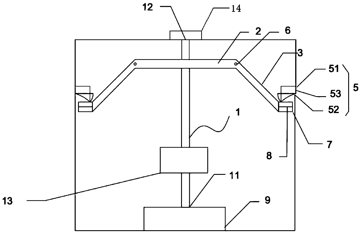
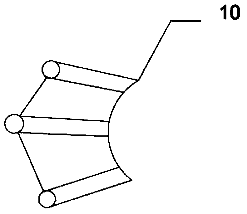
[0022] combined with figure 1 , a thrust mechanical energy output device, including a cylindrical body 12, an input shaft 1 located inside the cylindrical body 12, a turntable 2 pierced on the input shaft 1, and a plurality of centrally symmetrical rocker arms 3 are movable on the turntable 2 , the other end of the rocker arm 3 is provided with a load body 4, and the load body 4 makes a circular motion under the drive of the rocker arm 3; one end of the input shaft 1 is set as the input end 11, and the input end 11 is axially connected to the driving power mechanism 9, and It is connected with the equipment to be driven; the rocker arms 3 are connected through a three-axis hinge 10, and output rotational kinetic energy. A support bearing 13 is provided on the input shaft 11 and inside the cylindrical body 1 .

[0023] The rocker arm 3 is connected to the tu...


PUM


Abstract

The invention relates to a mechanical energy output mechanism which comprises an input shaft and a rotary disc arranged on the input shaft in a penetrating mode. A plurality of centrosymmetric rockerarms are movably arranged on the rotary disc. Load bodies are arranged at the other ends of the rocker arms, and the load bodies are driven by the rocker arms to carry out circular motion. Two ends ofthe input shaft are set as an input end and an output end respectively. The input end is coupled with a driving power mechanism, and the output end outputs power and is connected with to-be-driven equipment. By using the device, manufacturing and processing of a complex output structure are omitted, the manufacturing cost is saved, and the device can be widely applied to the technical field of mechanical equipment.

Description

technical field [0001] The invention relates to the technical field of mechanical equipment, in particular to a thrust mechanical energy output device. Background technique [0002] At present, the main ways that can generate thrust are: 1) Motor vehicles are driven by mechanical energy and generate friction with the road or rails, thereby making the vehicle move; 2) When various propellers are in the air, the blades are driven by mechanical energy, The lift is generated by the interaction force with the air, so that the helicopter with the propeller takes off; 3) The propeller on the ship is driven by mechanical energy, and the blade interacts with the water to generate thrust to make the ship sail; 4) All kinds of aviation jet engines are The fuel is detonated at the nozzle of the engine to generate a jet flow, which obtains recoil thrust and thus realizes flight. [0003] Helicopter blades need to obtain high lift, and the size of the blades is large, making the blades v...

Claims


Application Information

Patent Timeline
Patent Type & Authority Applications(China)
IPC IPC(8): F02B61/06H02K7/10
CPCF02B61/06H02K7/10
Inventor 李鸿远李佐如
Owner 李佐如
Why Eureka
Try Eureka