Movable cable wiring device head sealing device of reactor

A sealing device, wiring device technology, applied in the direction of reactor, nuclear reactor monitoring, reactor fuel element, etc., can solve problems such as operator damage, cable tray and cable occupying useful space on operating platform, etc.

Inactive Publication Date: 2002-12-11
WESTINGHOUSE ELECTRIC CORP
View PDF3 Cites 0 Cited by
  • Summary
  • Abstract
  • Description
  • Claims
  • Application Information

AI Technical Summary

Problems solved by technology

These cable trays and cables take up useful space on the operator's platform and are susceptible to operator damage during fuel changes

Method used


Image

  • Movable cable wiring device head sealing device of reactor
  • Movable cable wiring device head sealing device of reactor
  • Movable cable wiring device head sealing device of reactor

Examples


Embodiment Construction

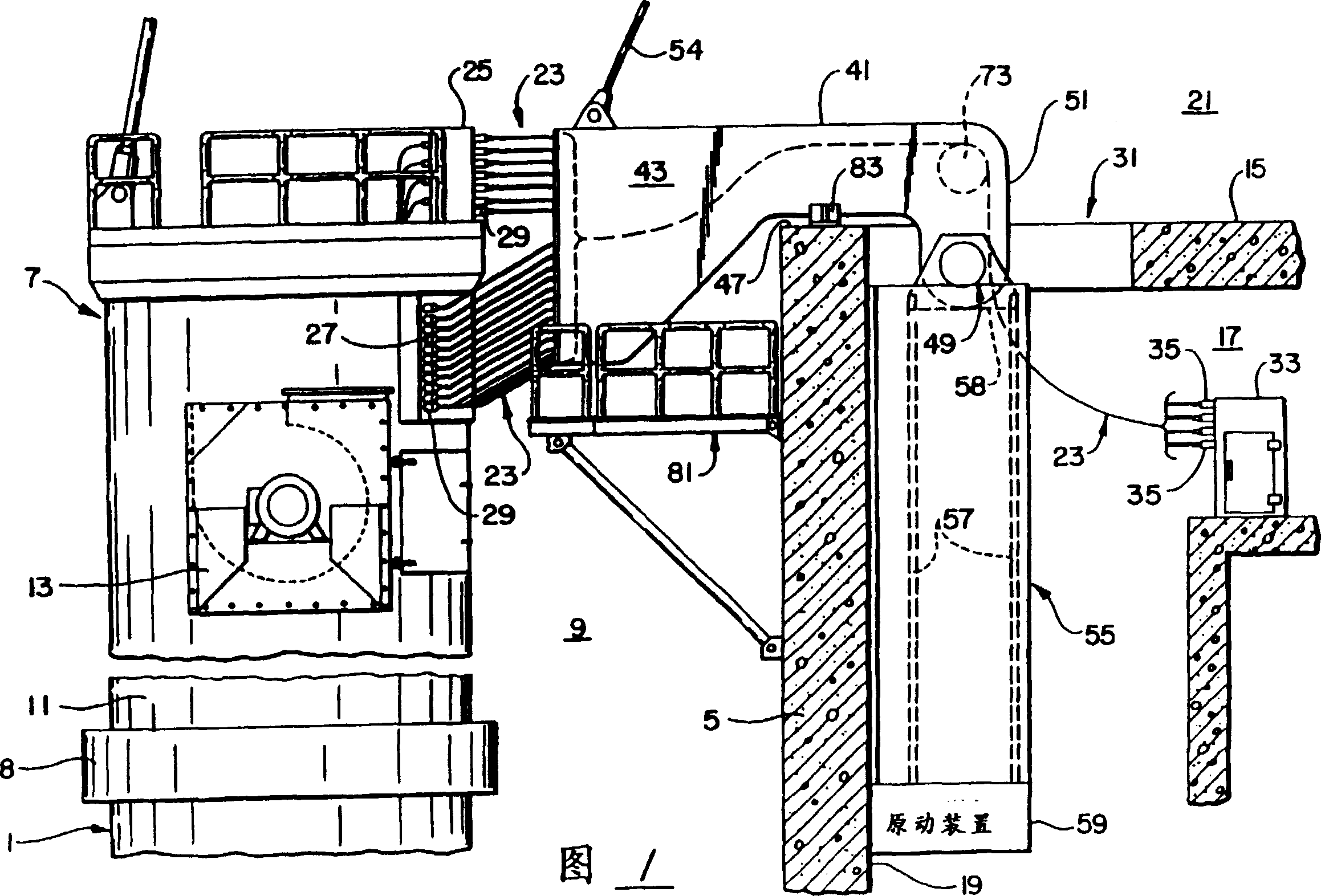
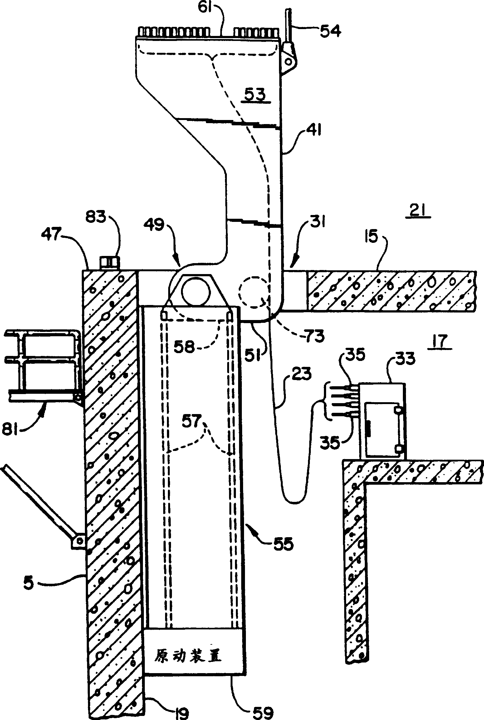
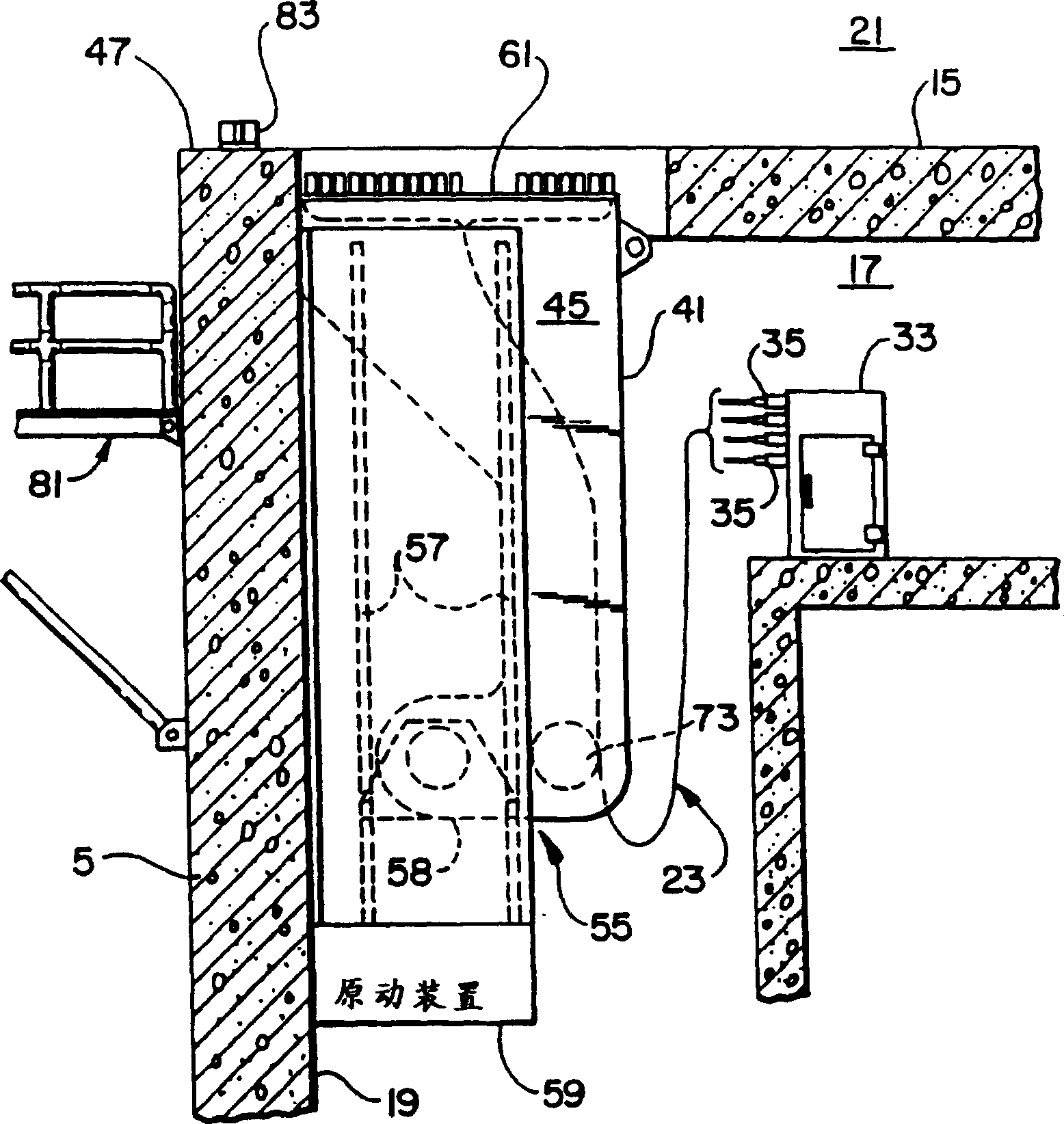
[0016] Referring now to the drawings, in which, for simplicity of illustration, similar structures common to the various figures throughout the specification will be designated with the same reference numerals, in FIGS. image 3 The cable routing device for nuclear reactor vessel according to the present invention is illustrated in three different positions. The nuclear reactor vessel 1 is located within an accident containment vessel (not shown). A cavity 9 is defined by a structural wall 5 which is spaced within the containment from the nuclear reactor vessel 1 and extends upwardly around the combined head seal 7 which is connected to the reactor vessel 1 at a flange 8 The top is insulated and cavity 9 is filled with water during reactor refueling. The combined head seal 7 includes a reactor vessel head 11, control rod drive mechanisms (CRDM's) (not shown), control rod position indicators (PRI's) (not shown), cooling fans 13 and other related components. The operating pla...


PUM


Abstract

A cable routing arrangement is provided for a nuclear reactor vessel located within a containment vessel. The structure inside the containment vessel is characterized by a wall (5) that surrounds the reactor vessel (1) on the near side and defines a chamber (9), an operating platform (15) outside the chamber, and a wall (5) on the platform ( 15), and a subspace (17) on the far side (19) of the wall (5) spaced from the near side, and an operating area (21) above the platform (15). The arrangement comprises a movable frame (41) supporting a plurality of cables (23) extending through the frame (41), each cable having a first end connectable to a head seal (7) on the reactor vessel and each cable has a second end located within the subspace (17). The frame (41) can move with the cables between the first position and the second position. The first position is located outside the subspace (17) and close to the head seal (7), and is used for connecting the cables (23) during normal operation of the reactor. to the position on the head seal (7) and the second position is located in the subspace where the cable (23) is removed from the head seal (7) during fuel replacement. In a preferred embodiment, the frame (41) straddles the top of the wall (5) in a generally horizontal orientation when in the first position, and pivots about an end distal to the head seal (7) to a generally vertical orientation. intermediate position, and, while maintaining a vertical orientation, is guided to a second position along a rail (57) within the subspace.

Description

[0001] The United States Government has rights in this invention pursuant to Cooperative Agreement DE-FC02-92-NE342657 awarded by the United States Department of Energy to the Advanced Reactor Association. technical field [0002] The present invention relates to cable trays for cables connected to a combined head package of a nuclear reactor, and in particular to allowing simultaneous removal of all power and control cables from the combined head package and storing them in one In a protected environment so that the operating platform in the containment does not at all block the cable trays for maintenance and refueling operations. Background technique [0003] Prior to refueling a nuclear power reactor, the integrated head seal (IHP) must be removed and stored. The combined head seal includes the reactor vessel head, control rod drive mechanisms (CRDM's), control rod position indicators (RPI's), cooling fans and other related components. A composite head seal for a nuclea...

Claims


Application Information

Patent Timeline
Patent Type & Authority Patents(China)
IPC IPC(8): G21C19/00G21C17/00
CPCG21C19/00Y02E30/30
Inventor 罗伯特·E·穆谢克丹尼尔·M·特朗布拉
Owner WESTINGHOUSE ELECTRIC CORP
Why Eureka
Try Eureka