Fire extinguishing device for high-voltage equipment

A technology of fire extinguishing device and high-voltage equipment, which is applied in the substation/distribution device casing, fire rescue and other directions, can solve the problems of poor fire extinguishing effect, inability to guarantee fire extinguishing effect, limited spray angle of fire extinguishing pipe, etc., to ensure fire extinguishing effect and functionality. Strong and reasonable structure

Inactive Publication Date: 2019-04-12
盐城紫环工业机械有限公司
View PDF0 Cites 8 Cited by
  • Summary
  • Abstract
  • Description
  • Claims
  • Application Information

AI Technical Summary

Problems solved by technology

[0003] 1. When the high-voltage switchgear burns and the internal circuit is burned, the entire high-voltage switchgear may have high-voltage current, and firefighters are prone to danger when taking the fire extinguisher;
[0004] 2. In order to ensure the heat dissipation effect, the existing high-voltage switchgear is usually equipped with cooling fans and other devices for ventilation and heat dissipation. When a fire occurs in the high-voltage switchgear, its good air circulation makes the combustion more intense, making the fire-fighting effect poor;
[0005] 3. Some high-voltage switch cabinets are equipped with a built-in fire extinguishing device for temperature control detection. When the combustion generates high temperature, the temperature sensor will perform induction feedback, so that the built-in fire extinguishing pipe can spray the fire. However, the spray angle of the fire extinguishing pipe is relatively limited and cannot Ensure good fire extinguishing effect

Method used


Image

  • Fire extinguishing device for high-voltage equipment
  • Fire extinguishing device for high-voltage equipment
  • Fire extinguishing device for high-voltage equipment

Examples


Embodiment Construction

[0023] The following will clearly and completely describe the technical solutions in the embodiments of the present invention with reference to the accompanying drawings in the embodiments of the present invention. Obviously, the described embodiments are only some, not all, embodiments of the present invention. Based on the embodiments of the present invention, all other embodiments obtained by persons of ordinary skill in the art without making creative efforts belong to the protection scope of the present invention.

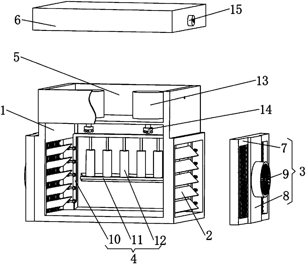
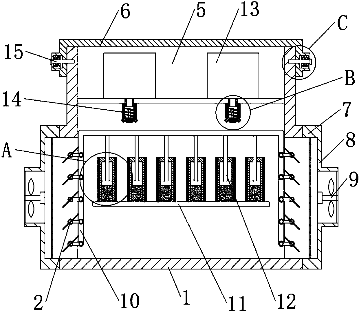
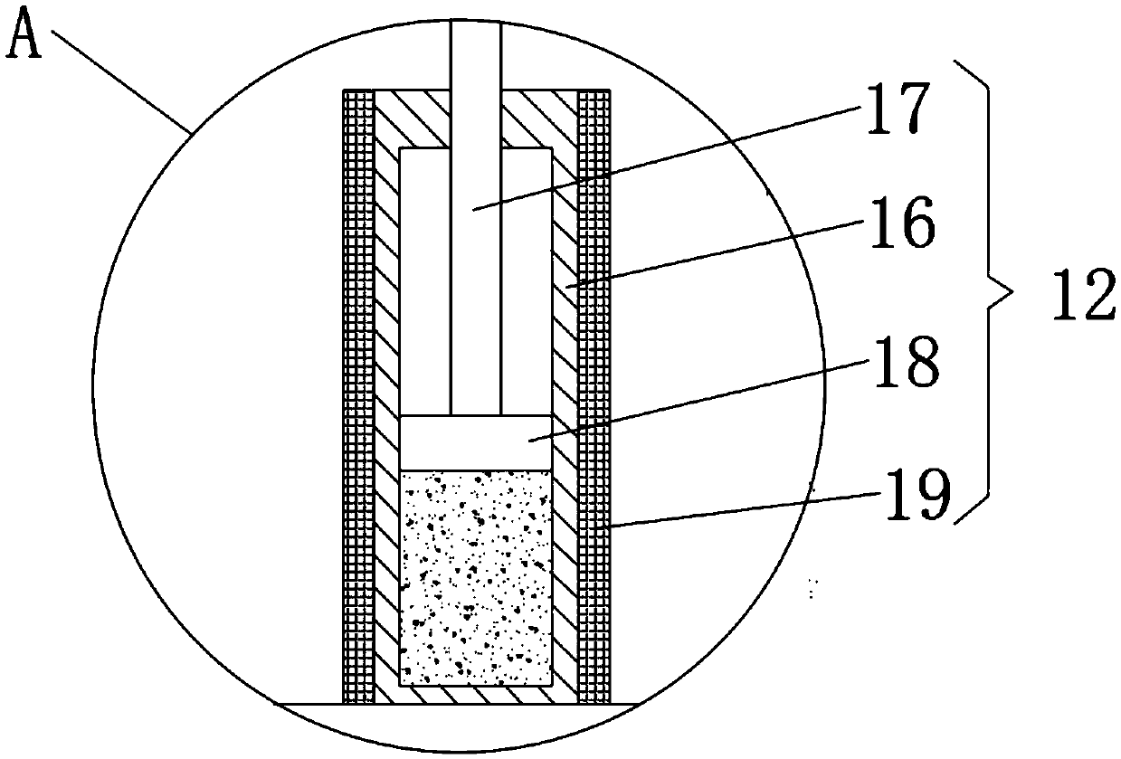
[0024] see Figure 1 to Figure 5 , the present invention provides a technical solution: a fire extinguishing device for high-voltage equipment, including a high-voltage switch cabinet 1, an adjusting fan group 2, a fan blade control device 4 and a spray head 14, and both sides of the high-voltage switch cabinet 1 are equipped with There is an adjusting fan group 2, which is composed of a plurality of elongated fan blades arranged vertically, each fan blade is ...


PUM


Abstract

The invention discloses a fire extinguishing device for high-voltage equipment. The fire extinguishing device comprises a high-voltage switch cabinet body, an adjustment fan group, a fan blade controldevice and injection heads, wherein a cooling plate group comprises a cooling frame, an electric fan support plate and an electric fan, the fan blade control device comprises a driving support, a temperature sensing device support seat and a temperature sensing device, the temperature sensing device comprises a temperature sensing tank, a top rod, a piston and a heat preservation layer, two fireextinguishing tanks are arranged above the high-voltage switch cabinet body and in a fire extinguishing device placement cavity, and the injection heads are connected with lower ends of the fire extinguishing tank. The fire extinguishing device placement cavity is formed in an upper end of the high-voltage switch cabinet, the fire extinguishing tank can be used for injecting CO2 into the high-voltage switch cabinet body when a fire is generated to achieve automatic fire extinguishing, and the fire extinguishing device is relatively safe; and the adjustment fan group can be closed under controlof the fan blade control device, oxygen containing content of the high-voltage switch cabinet is reduced, and combustion is effectively suppressed.

Description

technical field [0001] The invention relates to the technical field of fire extinguishing devices, in particular to a fire extinguishing device for high-voltage equipment. Background technique [0002] High-voltage switchgear refers to the role of on-off, control or protection in power system power generation, transmission, distribution, power conversion and consumption. By rationally configuring the components and their combinations with other electrical products, they are organically combined in a metal enclosure. Since the temperature of the electrical products inside the high-voltage switchgear will increase during operation, it is necessary to ensure good ventilation to ensure the working efficiency of the electrical products and prevent burning caused by excessive temperature; in order to prevent fires caused by accidents in the high-voltage switchgear , usually a common hand-held jetting carbon dioxide fire extinguisher is placed in the high-voltage switchgear for us...

Claims


Application Information

Patent Timeline
Patent Type & Authority Applications(China)
IPC IPC(8): H02B1/30H02B1/28A62C3/16A62C37/36
CPCH02B1/30A62C3/16A62C37/36H02B1/28
Inventor 冯文君
Owner 盐城紫环工业机械有限公司
Why Eureka
Try Eureka