Bidirectional block hopping scanning multidirectional prediction methods in bandwidth compression

A bandwidth compression and prediction method technology, applied in the multimedia field, can solve the problems of inability to obtain prediction reference and prediction results, poor effect, inability to obtain, etc., and achieve the effect of reducing theoretical limit entropy, small prediction residual error, and high compression rate

Inactive Publication Date: 2019-04-12
XIAN CREATION KEJI CO LTD
View PDF0 Cites 0 Cited by
  • Summary
  • Abstract
  • Description
  • Claims
  • Application Information

AI Technical Summary

Problems solved by technology

Therefore, when predicting, because more reference directions cannot be obtained, better prediction references and prediction results cannot be obtained
It can be seen that the above raster scan is not optimal, and compared with flat areas, raster scan is less effective in predicting boundaries and complex texture areas

Method used


Image

  • Bidirectional block hopping scanning multidirectional prediction methods in bandwidth compression
  • Bidirectional block hopping scanning multidirectional prediction methods in bandwidth compression
  • Bidirectional block hopping scanning multidirectional prediction methods in bandwidth compression

Examples


Embodiment 1

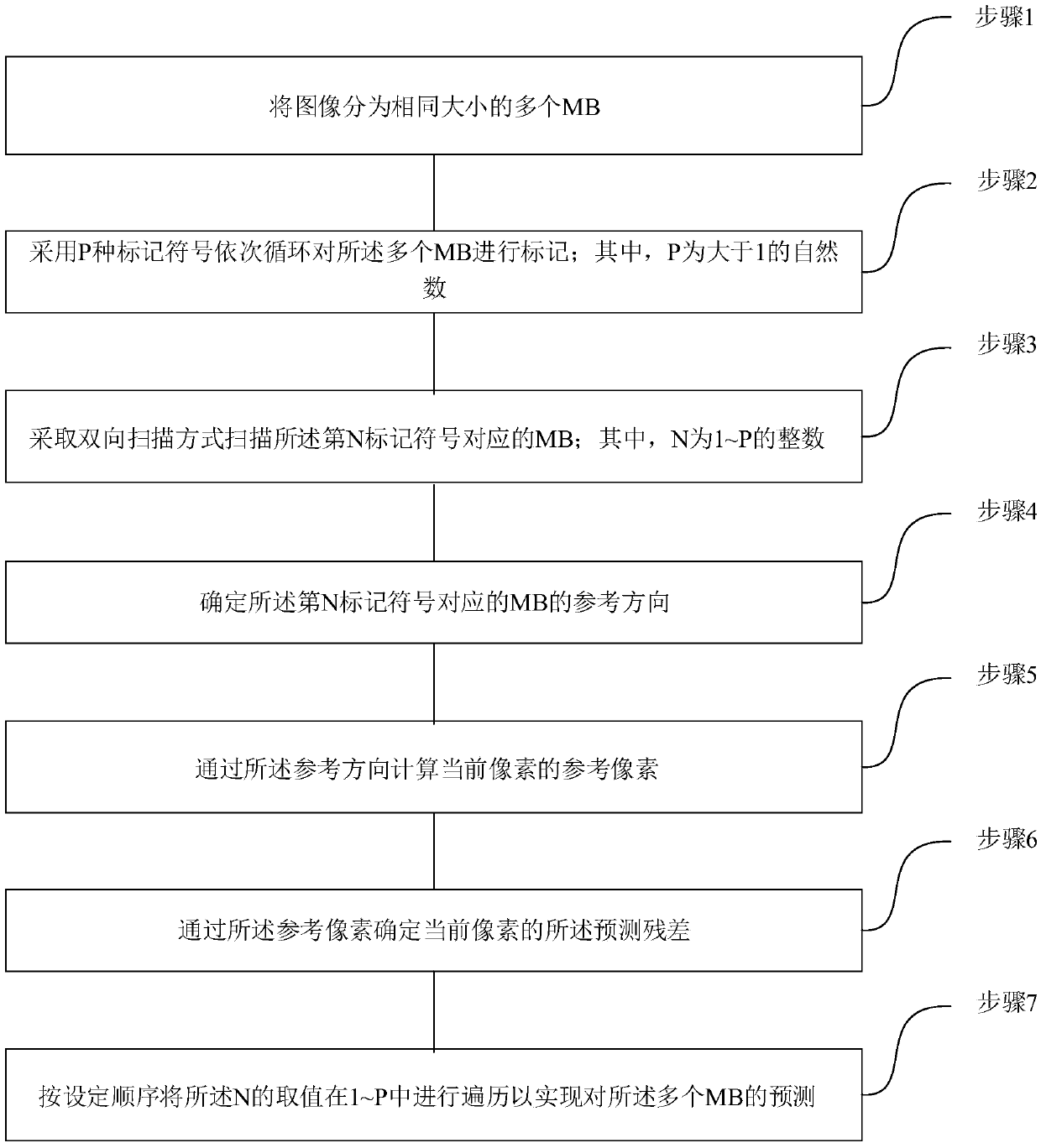
[0049] See figure 1 , figure 1 It is a flow chart of a bidirectional block skip scanning multi-directional prediction method in bandwidth compression provided by an embodiment of the present invention. The method comprises the steps of:

[0050] Step 1. Divide the image into multiple MBs of the same size;

[0051] Step 2, using P types of marking symbols to sequentially mark the multiple MBs; wherein, P is a natural number greater than 1;

[0052] Step 3. Scanning the MB corresponding to the Nth marker symbol in a bidirectional scanning manner; wherein, N is an integer from 1 to P;

[0053] Step 4. Determine the reference direction of the MB corresponding to the Nth marker symbol;

[0054] Step 5, calculating the reference pixel of the current pixel through the reference direction;

[0055] Step 6. Determine the prediction residual of the current pixel through the reference pixel of the current pixel;

[0056] Step 7. Go through the values ​​of N in 1~P according to the ...

Embodiment 2

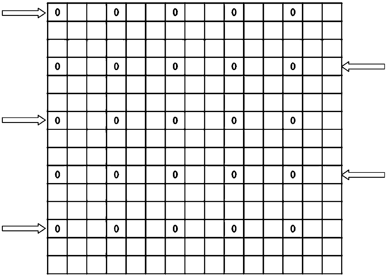
[0098] See Figure 2 to Figure 7 , figure 2 A schematic diagram of an image MB division mark provided by an embodiment of the present invention; image 3 A schematic diagram of bi-directional image scanning provided by an embodiment of the present invention; Figure 4 A schematic diagram of the original position of the current MB and the closest reference MB provided by the embodiment of the present invention; Figure 5 A schematic diagram of the zoomed-in position of the current MB and the closest reference MB provided by the embodiment of the present invention; Figure 6 A schematic diagram of the current MB full reference direction provided by the embodiment of the present invention; Figure 7 A schematic diagram of the current MB without a lower reference direction provided by the embodiment of the present invention; Figure 8 A schematic diagram of determining a second reference pixel for a current pixel provided by an embodiment of the present invention. In this em...


PUM


Abstract

The invention relates to bidirectional block hopping scanning multidirectional prediction methods in bandwidth compression. A method comprises the steps of dividing an image into a plurality of MBs ofthe same size; marking the plurality of MBs circularly in sequence through adoption of P mark symbols, wherein the P is a natural number greater than 1; scanning the MBs corresponding to an Nth marksymbol in a bidirectional scanning mode, wherein the N is an integer between 1 to P; determining reference directions of the MBs corresponding to the Nth mark symbol; computing reference pixels of a current pixel through utilization of the reference directions; determining predicted residual errors of the current pixel through utilization of the reference pixels of the current pixel; and traversing a value of the N in the 1-P according to a set sequence, thereby predicting the plurality of MBs. According to the method, through adoption of a block hopping scanning method, the predicted pixel value of the current pixel is determined. Compared with an existing method, the method has the advantages that more reference directions can be obtained for the MBs, and predicted theoretical limit entropy is further reduced.

Description

technical field [0001] The invention relates to the field of multimedia technology, in particular to a method for bidirectional block-hopping scanning and multi-directional prediction in bandwidth compression. Background technique [0002] With the increase of video image resolution, it needs to occupy more storage space and transmission bandwidth. In this case, it is particularly necessary to use the bandwidth compression technology in the chip to improve the image storage space and transmission bandwidth. [0003] Different from port type compression (such as H.265), the goal of on-chip bandwidth compression is to increase the compression factor as much as possible and reduce DDR occupation with a smaller logic area cost. Bandwidth compression is mainly composed of four parts, including: prediction module, quantization module, code control module and entropy coding module. Among them, the prediction module is an important module, which uses the spatial redundancy between ...

Claims


Application Information

Patent Timeline
IPC IPC(8): H04N19/176H04N19/182H04N19/42H04N19/50
CPCH04N19/176H04N19/182H04N19/42H04N19/50
Inventor 张莹冉文方罗瑜
Owner XIAN CREATION KEJI CO LTD
Why Eureka
Try Eureka