Predictive Methods for Video Compression

A technology of video compression and prediction method, which is applied in digital video signal modification, image communication, electrical components, etc. It can solve the problems of not making full use of pixel texture correlation, predicting pixel components that are easy to be misjudged, and cannot be obtained, so as to achieve good prediction Effect of direction correction, reduction of theoretical limit entropy, effect of reducing possibility

Active Publication Date: 2020-07-10
NANJING HUAIYE INFORMATION TECH CO LTD
View PDF6 Cites 0 Cited by
  • Summary
  • Abstract
  • Description
  • Claims
  • Application Information

AI Technical Summary

Problems solved by technology

[0004] However, the existing texture-related prediction methods have the following problems due to the small number of reference directions: 1) The components of the predicted pixels are easy to be misjudged, which affects the prediction results; 2) The prediction methods do not make full use of the correlation between pixel textures and cannot Further reduce the theoretical limit entropy and computational complexity
Therefore, when predicting, because more reference directions cannot be obtained, better prediction references and prediction results cannot be obtained
It can be seen that the above-mentioned raster scan is not optimal, and compared with flat areas, raster scan is less effective in predicting boundaries and complex texture areas

Method used


Image

  • Predictive Methods for Video Compression
  • Predictive Methods for Video Compression
  • Predictive Methods for Video Compression

Examples


Embodiment 1

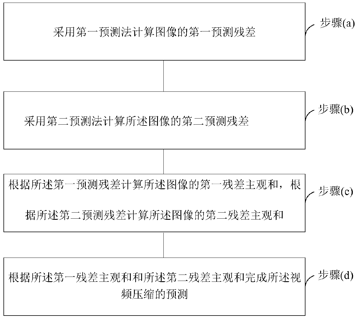
[0056] See figure 1 , figure 1 It is a schematic flowchart of a video compression prediction method provided by an embodiment of the present invention.

[0057] A method for predicting video compression, comprising the following steps:

[0058] (a) adopting the first prediction method to calculate the first prediction residual of the image;

[0059] (b) calculating a second prediction residual of the image using a second prediction method;

[0060] (c) calculating a first residual subjective sum of the image according to the first prediction residual, and calculating a second residual subjective sum of the image according to the second prediction residual.

[0061] (d) performing prediction of the video compression according to the first residual subjective sum and the second residual subjective sum.

[0062] In the embodiment of the present invention, two prediction residual results of the image are respectively calculated by two prediction methods, and two different residu...

Embodiment 2

[0064] In this embodiment, on the basis of the foregoing embodiments, the video compression prediction method will be described in detail. The forecasting method includes the following steps:

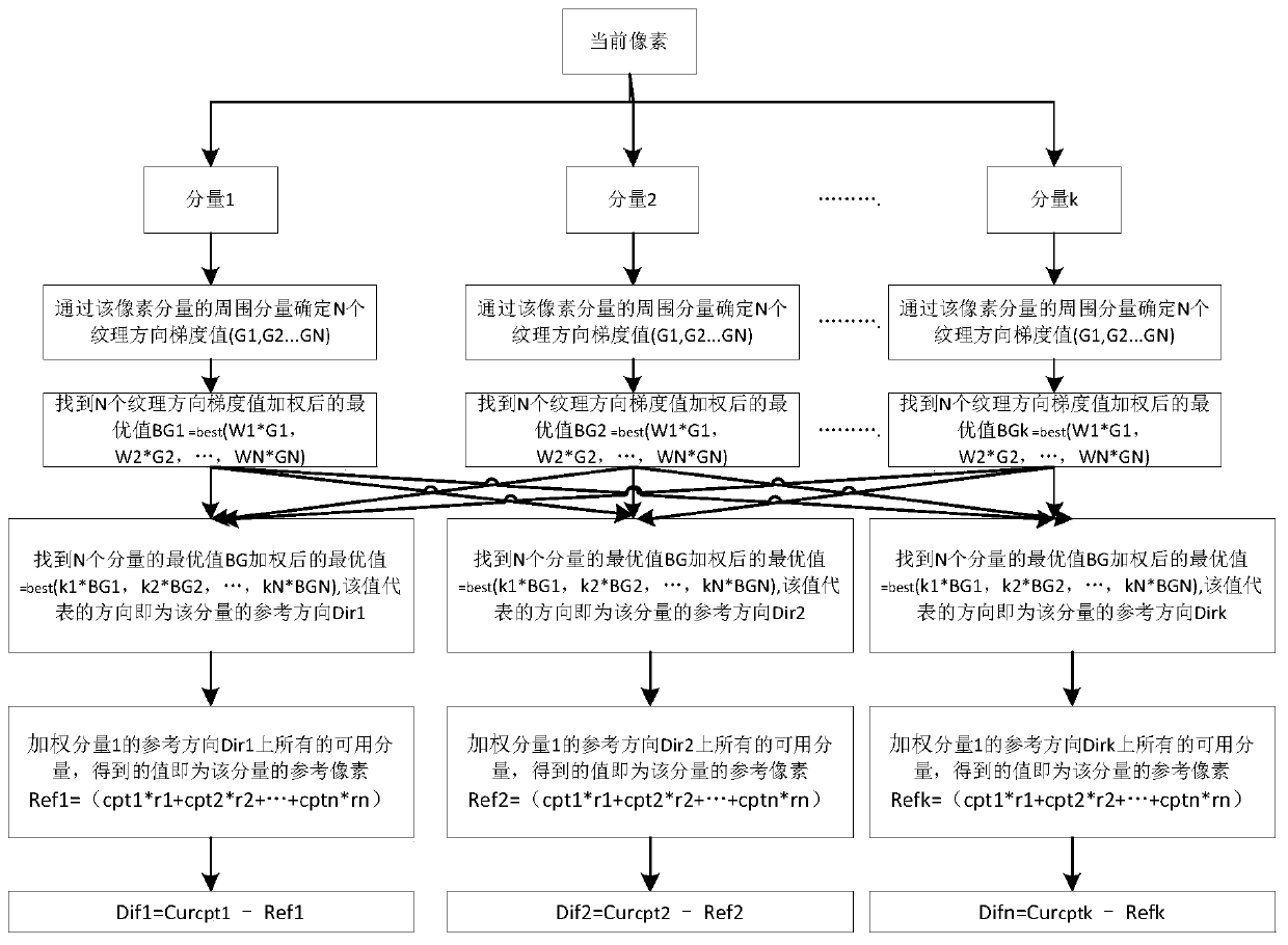
[0065] (S10) Calculate the first prediction residual of the image by using the first prediction method. See figure 2 , figure 2 It is a schematic diagram of an algorithm principle of a first prediction method of a video compression prediction method provided by an embodiment of the present invention.

[0066] (S101) Obtain multiple components of the current pixel of the image.

[0067] In this embodiment, it is assumed that the current pixel has k components, k≥1.

[0068] (S102) Determine gradient values ​​of texture directions of the plurality of components.

[0069] For each component of the current pixel, by determining the surrounding components of each component, the gradient values ​​of the N texture directions of each component are determined, and the gradient values ​​ar...

Embodiment 3

[0168] In this embodiment, on the basis of the foregoing embodiments, the current pixel is divided into three components of Y, U, and V to describe the first prediction method in detail, and the specific implementation manner is as follows.

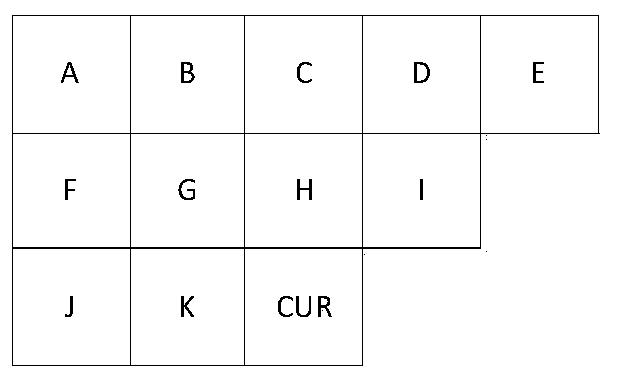
[0169] (S30) see Figure 11 , Figure 11 It is an algorithm schematic diagram of the first prediction method of another video compression prediction method provided by the embodiment of the present invention; the current pixel is divided into three components, namely component Y, component U, and component V.

[0170] (S31) Determine the gradient values ​​G1, G2, and G3 of the three texture directions through the surrounding components of the three components of the current pixel.

[0171] See Figure 12 , Figure 12 A schematic diagram of a gradient value calculation of a video compression prediction method provided by an embodiment of the present invention; in a specific embodiment, for the three components of Y, U, and V, ABS (K-H) ...


PUM


Abstract

The invention relates to a prediction method of video compression. The method comprises the following steps that (a) a first prediction residual error of an image is calculated via a first predictionmethod; (b) a second prediction residual error of the image is calculated via a second prediction method; (c) a subjective sum of the first residual error of the image is calculated according to the first prediction residual error, and a subjective sum of the second residual error of the image is calculated according to the second prediction residual error; and (d) video compression prediction iscompleted according to the subjective sum of the first residual error and the subjective sum of the second residual error. A more proper prediction method is selected from two methods, and a predictedtheoretical limit entropy can be reduced.

Description

technical field [0001] The invention belongs to the field of compression coding, and in particular relates to a video compression prediction method. Background technique [0002] There is a lot of redundancy in the video data, that is, there is a strong correlation between the pixel data of the image. Using these correlations, the data of some pixels can be deduced from the data of another part of pixels. As a result, the amount of video data can be greatly compressed, which is beneficial to transmission and storage. [0003] The prediction method is the simplest and most practical video compression coding method. At this time, what is transmitted after compression coding is not the sampling amplitude of the pixel itself, but the difference between the predicted value and the actual value of the sampling. A large number of statistics show that there is a correlation between adjacent pixels of the same image, or that these pixel values ​​are similar, and there is also a stro...

Claims


Application Information

Patent Timeline
Patent Type & Authority Patents(China)
IPC IPC(8): H04N19/176H04N19/182H04N19/42H04N19/50
CPCH04N19/176H04N19/182H04N19/42H04N19/50
Inventor 杨剑叶恒陆浩杭伟陆晓艳田林海李雯岳庆冬
Owner NANJING HUAIYE INFORMATION TECH CO LTD
Why Eureka
Try Eureka