Engine cylinder deactivation mechanism

A technology of engine and sleeve, applied in the direction of engine components, engine control, machine/engine, etc., can solve the problem of high fuel-saving pressure, achieve the effect of reducing fuel consumption and realizing the fuel-saving effect of the whole vehicle

Active Publication Date: 2019-04-16
ANHUI JIANGHUAI AUTOMOBILE GRP CORP LTD
View PDF5 Cites 2 Cited by
  • Summary
  • Abstract
  • Description
  • Claims
  • Application Information

AI Technical Summary

Problems solved by technology

This makes the fuel-saving pressure of traditional fuel vehicles extremely high. For fuel vehicles, how to reduce the fuel consumption of the

Method used


Image

  • Engine cylinder deactivation mechanism
  • Engine cylinder deactivation mechanism
  • Engine cylinder deactivation mechanism

Examples


Example Embodiment

[0036] In order to enable those skilled in the art to better understand the technical solution of the present invention, the solution will be further described in detail below in conjunction with specific embodiments.

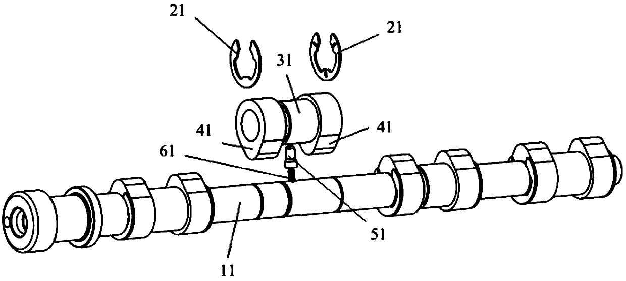
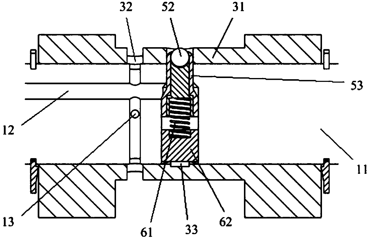
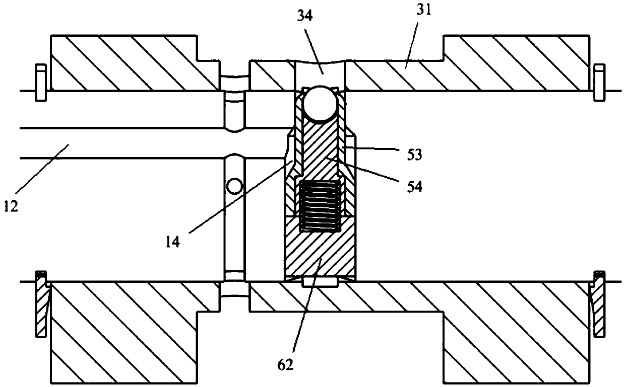
[0037] like Figure 1 to Figure 10 As shown, the embodiment of the present invention provides an engine cylinder deactivation mechanism, which includes a camshaft 11, a sleeve 31, a cam 41 and a thrust plate 21, the sleeve 31 is sleeved on the camshaft 11, the The inner wall of the sleeve 31 is rotatably matched with the outer surface of the camshaft 11, and the cam 41 is fixedly arranged on the sleeve 31; the two thrust plates 21 are oppositely arranged on the camshaft 11, and respectively It is in contact with both ends of the sleeve 31; a locking hole 34 is provided on the outer surface of the sleeve, and a receiving hole corresponding to the locking hole 34 is provided on the camshaft. A locking mechanism is provided in the accommodating hole, and the lock...


PUM


Abstract

The invention provides an engine cylinder deactivation mechanism. The mechanism comprises a cam shaft, a sleeve, a cam and thrust plates, wherein the sleeve sleeves the cam shaft, the inner wall of the sleeve is rotationally matched with the outer surface of the cam shaft, and the cam is fixedly arranged on the sleeve; the two thrust plates are oppositely arranged on the cam shaft and are in blocking connection with the two ends of the sleeve correspondingly; a locking hole is formed in the outer surface of the sleeve, the cam shaft is provided with a containing hole corresponding to the locking hole, a locking mechanism is arranged in the containing hole, and the locking mechanism is provided with a limiting piece which can extend into the locking hole; the limiting piece is provided witha locking position and an unlocking position, in the locking position, the limiting piece extends into the locking hole to realize the locking between the sleeve and the cam shaft; and in the unlocking position, the limiting piece retracts into the containing hole to release locking between the sleeve and the cam shaft. According to the engine cylinder deactivation mechanism, the oil consumptionof an engine can be effectively reduced, and oil saving of a whole automobile can be well achieved.

Description

technical field [0001] The invention relates to the technical field of vehicle engines, in particular to an engine cylinder deactivation mechanism. Background technique [0002] Against the backdrop of increasingly stringent fuel consumption standards, auto companies are facing increasing pressure to save fuel. This makes the fuel-saving pressure of traditional fuel vehicles extremely high. For fuel vehicles, how to reduce the fuel consumption of the engine to realize fuel-saving of the whole vehicle has become a technical problem urgently to be solved by those skilled in the art. Contents of the invention [0003] The object of the present invention is to provide an engine cylinder deactivation mechanism to reduce the fuel consumption of the engine and realize the fuel saving of the whole vehicle. [0004] To achieve the above object, the present invention provides the following technical solutions: [0005] An engine cylinder deactivation mechanism, which includes a ca...

Claims


Application Information

Patent Timeline
IPC IPC(8): F01L13/00F02D13/06
CPCF01L13/0005F02D13/06
Inventor 王锦艳陈龙华李海鹏颜伟张鑫
Owner ANHUI JIANGHUAI AUTOMOBILE GRP CORP LTD
Why Eureka
Try Eureka