Subway top suspension device

A suspension device, subway technology, applied in lighting devices, fixed lighting devices, lighting auxiliary devices, etc., can solve the problems of reducing installation efficiency, shaking damage to the lamp body, reducing the service life of the lamp body, etc., to improve the efficiency of installation, avoid The effect of shaking damage and improving the service life

Inactive Publication Date: 2019-04-16
王世勇
View PDF10 Cites 1 Cited by
  • Summary
  • Abstract
  • Description
  • Claims
  • Application Information

AI Technical Summary

Problems solved by technology

[0002] Subway is a rapid and large-capacity urban rail transit mode that is gradually developed along the surface railway system. Its lines are usually laid in underground tunnels, and some are outside the city center, from underground to ground or The way of laying on the viaduct, but the existing subway top suspension device still has the following problems, 1. When the maintenance personnel repair the lamp body, they cannot fix the lamp body for maintenance, and need to hold the lamp body for maintenance, which is troublesome , which reduces the efficiency of maintenance. 2. When the lamp body is illuminated, it cannot be fixed. The lamp body is prone to shaking and damage during the subway driving, which reduces the service life of the lamp body. 3. When other parts need to be connected with the suspension It is more troublesome to connect the skeleton, which increases the labor load of the installers and reduces the efficiency of the installation

Method used


Image

  • Subway top suspension device
  • Subway top suspension device
  • Subway top suspension device

Examples


Embodiment Construction

[0020] The following will clearly and completely describe the technical solutions in the embodiments of the present invention with reference to the accompanying drawings in the embodiments of the present invention. Obviously, the described embodiments are only some, not all, embodiments of the present invention.

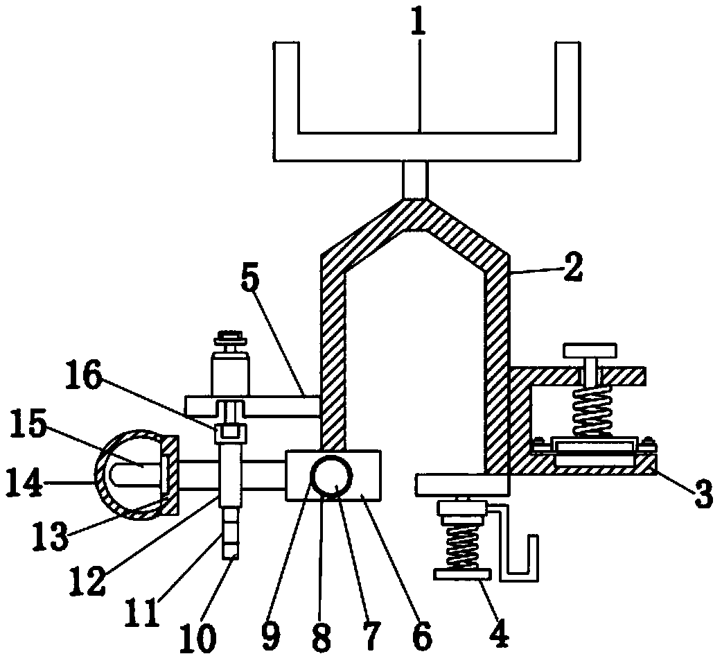
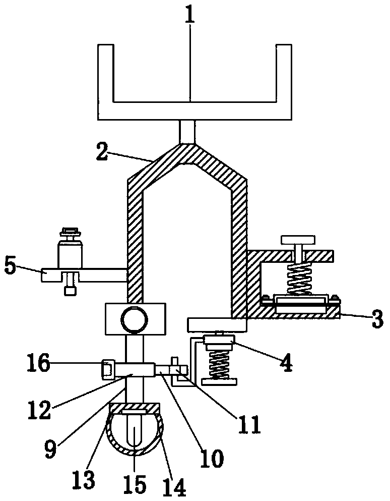
[0021] refer to Figure 1-5 , a subway top suspension device, including a mounting base 1, through which the suspension frame 2 can be fixed, and the outer walls of the left and right sides of the mounting base 1 are provided with circular through holes, and the mounting base 1 The bottom end is welded with a suspension frame 2, and the left side of the bottom end of the suspension frame 2 is welded with a connecting seat 6, and the inside of the connecting seat 6 is provided with a jack 8, through which the installation and rotation of the rotating rod 7 can be realized , the inside of the jack 8 is plugged with a rotating rod 7, the left side of the rotating rod 7 ...


PUM


Abstract

The invention discloses a subway top suspension device, which comprises a mounting seat, wherein a suspension framework is welded at the bottom of the mounting seat, a connecting seat is welded at a left side of the bottom of the suspension framework, a jack is formed in the connecting seat, a lamp holder is welded at the left side of a cross rod, a lamp body is arranged at the left side of the lamp holder, a lamp body fixing device is welded at the bottom of the left side of the suspension framework, a hook mechanism is welded at a right side of the bottom of the suspension framework, and a fixing mechanism is welded at the bottom of the right side of the suspension framework. By the adoption of the subway top suspension device, the lamp body can be fixed and maintained by maintenance personnel when the lamp body is maintained through the lamp body fixing device, the lamp body does not need to be held by hands for maintenance, the maintenance is easy, the maintenance efficiency is improved, the lamp body can be fixed when illuminating by the hook mechanism, the phenomenon that the lamp body is shaken and damaged in a running process of the subway is avoided, and the service life of the lamp body is prolonged.

Description

technical field [0001] The invention relates to the technical field of subway vehicles, in particular to a subway top suspension device. Background technique [0002] Subway is a rapid and large-capacity urban rail transit mode that is gradually developed along the surface railway system. Its lines are usually laid in underground tunnels, and some are outside the city center, from underground to ground or The way of laying on the viaduct, but the existing subway top suspension device still has the following problems, 1. When the maintenance personnel repair the lamp body, they cannot fix the lamp body for maintenance, and need to hold the lamp body for maintenance, which is more troublesome , which reduces the efficiency of maintenance. 2. When the lamp body is illuminated, it cannot be fixed. The lamp body is prone to shaking and damage during the subway running, which reduces the service life of the lamp body. 3. When other parts need to be connected with the suspension I...

Claims


Application Information

Patent Timeline
Patent Type & Authority Applications(China)
IPC IPC(8): F21S8/06F21V21/116F21W107/10
CPCF21S8/063F21V21/116F21W2107/10
Inventor 王世勇路林海王紫珊李平云顾明
Owner 王世勇
Why Eureka
Try Eureka