New energy battery plate qualification detection device
A detection device and battery board technology, applied in the direction of measuring devices, instruments, etc., can solve the problems of new energy battery board movement, impossible new energy battery board fixed detection, new energy battery board detection inaccuracy, etc., to achieve good results and avoid loose effect
- Summary
- Abstract
- Description
- Claims
- Application Information
AI Technical Summary
Problems solved by technology
Method used
Image
Examples
Embodiment 1
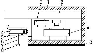
[0019] A qualified detection device for new energy battery boards, comprising a detection box 1, a moving mechanism 2 is fixedly connected to the top of the inner cavity of the testing box 1, the left side of the moving mechanism 2 penetrates and extends to the left side of the testing box 1, and the moving mechanism 2 The bottom is fixedly connected with a mechanical arm 3, and the bottom of the inner box of the detection box 1 is fixedly connected with a qualified detection mechanism 9. The left side of the detection box 1 is provided with a fixed plate 4, and both sides of the inner cavity of the fixed plate 4 are movably connected with transmission wheels 6. , the surface of the transmission wheel 6 is connected by a transmission belt 5, the bottom of the fixed plate 4 is fixedly connected with a support column 7, the bottom of the support column 7 is fixedly connected with a non-slip pad 8, and the bottom of the detection box 1 is fixedly connected with a rubber pad 10.
...
Embodiment 2
[0022] On the basis of Embodiment 1, the moving mechanism 2 includes a movable box 16, and the right side of the movable box 16 inner chamber is fixedly connected with a motor 14, and the top and bottom of the motor 14 are fixedly connected with the movable box 16 by a bracket 13, The output end of the motor 14 is movably connected with a screw rod 17, the left side of the screw rod 17 is movably connected with the joint of the movable box 16 through a movable base 18, the surface of the screw rod 17 is threadedly connected with a screw sleeve 15, and the top of the screw sleeve 15 is fixedly connected with a sliding Rod 12, the top of the movable box 16 cavity is provided with a chute 11 that is compatible with the slide bar 12, the bottom of the screw sleeve 15 penetrates and extends to the bottom of the movable box 16, and the bottom of the screw sleeve 15 is fixedly connected with the mechanical arm 3 .
[0023] When the moving mechanism 2 is running, the motor 14 runs, th...
Embodiment 3
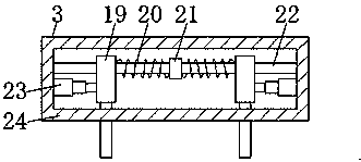
[0025] On the basis of Embodiment 1 or Embodiment 2, the mechanical arm 3 includes a bearing box 24, the top of the inner cavity of the bearing box 24 is fixedly connected with a movable rod 22, and the center of the surface of the movable rod 22 is sleeved with a baffle plate 21. Both sides of the surface of the rod 22 are equipped with telescopic splints 19, the inner side of the telescopic splints 19 and the junction of the baffle plate 21 are sleeved with a first spring 20, and the bottoms on both sides of the inner cavity of the carrying case 24 are fixedly connected with cylinders 23, The output end of the cylinder 23 is fixedly connected with the telescopic splint 19 , and the bottom of the telescopic splint 19 penetrates and extends to the bottom of the bearing box 24 .
[0026] When the mechanical arm 3 is running, the telescopic splint 19 is driven by the cylinder 23 to move left and right, the movable rod 22 is used to limit the telescopic splint 29 to move left and ...
PUM
 Abstract
Description
Claims
Application Information
 - R&D
- Intellectual Property
- Life Sciences
- Materials
- Tech Scout
- Unparalleled Data Quality
- Higher Quality Content
- 60% Fewer Hallucinations
Browse by: Latest US Patents, China's latest patents, Technical Efficacy Thesaurus, Application Domain, Technology Topic, Popular Technical Reports.
© 2025 PatSnap. All rights reserved.Legal|Privacy policy|Modern Slavery Act Transparency Statement|Sitemap|About US| Contact US: help@patsnap.com


