

Method for measuring flood discharge atomization rainfall capacity
A technique of rainfall and flood discharge, applied in the direction of rainfall/precipitation gauge, measuring device, meteorology, etc., can solve the problems of not being able to obtain rainfall, not being able to obtain rainfall, not being able to obtain rainfall, etc., and achieve the effect of accurate data
- Summary
- Abstract
- Description
- Claims
- Application Information
AI Technical Summary
Problems solved by technology
Method used
Image

Examples
Embodiment Construction
[0046] The embodiments of the present invention will be described in detail below in conjunction with the accompanying drawings, so that the advantages and features of the present invention can be more easily understood by those skilled in the art, so as to define the protection scope of the present invention more clearly.
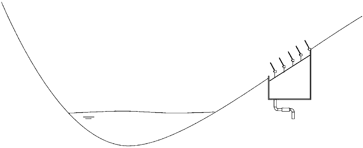
[0047] Specifically, the present invention provides a method for measuring and calculating the atomized rainfall of flood discharge, comprising the following steps:
[0048] (M1) Select a typical rain collection area at the atomization site;
[0049] (M2) Excavate a 1m×1m pit on the underlying surface of the rain collection area according to the existing slope;
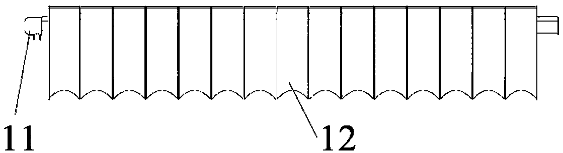
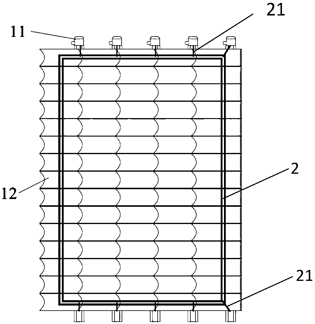
[0050] (M3) Make a device for measuring and calculating the atomized rainfall of flood discharge according to the slope;
[0051] (M4) Install a device for measuring and calculating the atomized rainfall of flood discharge in the tank;
[0052] (M5) for rainfall measurement.
[0053] The above-...
PUM
| Property | Measurement | Unit |
|---|---|---|
| Length | aaaaa | aaaaa |
| Width | aaaaa | aaaaa |
| Radius | aaaaa | aaaaa |
Abstract
Description
Claims
Application Information