Network management system generating virtual network map and related methods

a network management system and network management system technology, applied in the field of computer networking, can solve the problems of reducing performance, critical redundancy, requiring more complex arrangements, and many computing devices being left unconnected to the network or with reduced bandwidth

Active Publication Date: 2015-02-12
HARRIS CORP
View PDF5 Cites 80 Cited by
  • Summary
  • Abstract
  • Description
  • Claims
  • Application Information

AI Technical Summary

Benefits of technology

[0012]In view of the foregoing background, it is therefore an object of the present invention to provide a network management system that may accurately depict virtual and physical networks in a detailed and dynamic fashion.

Problems solved by technology

Modern networks can include thousands of computing devices in local or geographically remote locations and a large number of subnetworks and thus require more complex arrangements.
As with any complex network, device failure can cause reduction of performance, key services, and critical redundancy.
For example, if a network switch fails, numerous computing devices may be left unconnected to the network or left with reduced bandwidth.
Typically, the solution is simple involving hardware replacement; however, it is more complex to identify the root cause of the failure.
For example, a common scenario is that a portion of a large network experiences a lack of functionality such as reachability, and the originating cause can be any number of problems, thereby causing the information technology (IT) personnel to have to sequentially attempt methods to diagnose the problem, an effective but lengthy process.
At present, this method cannot produce a logical hierarchy of distinct logical views with or without overlapping IP address space.
However, it cannot create multiple logical levels or one where IP addressing space is overlapping between multiple logical levels.
Thus, host devices on the same given VLAN can communicate with each other, but cannot communicate with host devices in a different VLAN without an interconnecting router.
Network mapping software could resolve this by connecting to separate interfaces, but this has several problems concerning scale and connecting to all VLANs.
Drawing a network with VLANs from inquiries only within the data plane is also difficult.
Current network management and network mapping software have difficulty in displaying such diverse discontinuous network logic possibilities that VLANs can support, particularly when router virtualization is involved.
A single network router may have virtual routers with overlapping IP address space that may indicate the same devices or may not which creates difficulty for existing network management systems.
For example, network mapping software working within a data plane is not aware of the virtual networking configuration, thus the network displayed may include breaks and improper visibility of host computers or network devices.
Nevertheless, this method may not visualize a multiple virtual domain network or show multiple logical connections with a single physical entity as the technology relates to host computer virtualization and not network device virtualization.
It cannot resolve multiple overlapping IP address space concerns and create a correct view of a network which works at multiple independent logical isolated paths.

Method used


Image

  • Network management system generating virtual network map and related methods
  • Network management system generating virtual network map and related methods
  • Network management system generating virtual network map and related methods

Examples


Embodiment Construction

[0042]The present invention will now be described more fully hereinafter with reference to the accompanying drawings, in which preferred embodiments of the invention are shown. This invention may, however, be embodied in many different forms and should not be construed as limited to the embodiments set forth herein. Rather, these embodiments are provided so that this disclosure will be thorough and complete, and will fully convey the scope of the invention to those skilled in the art. Like numbers refer to like elements throughout.

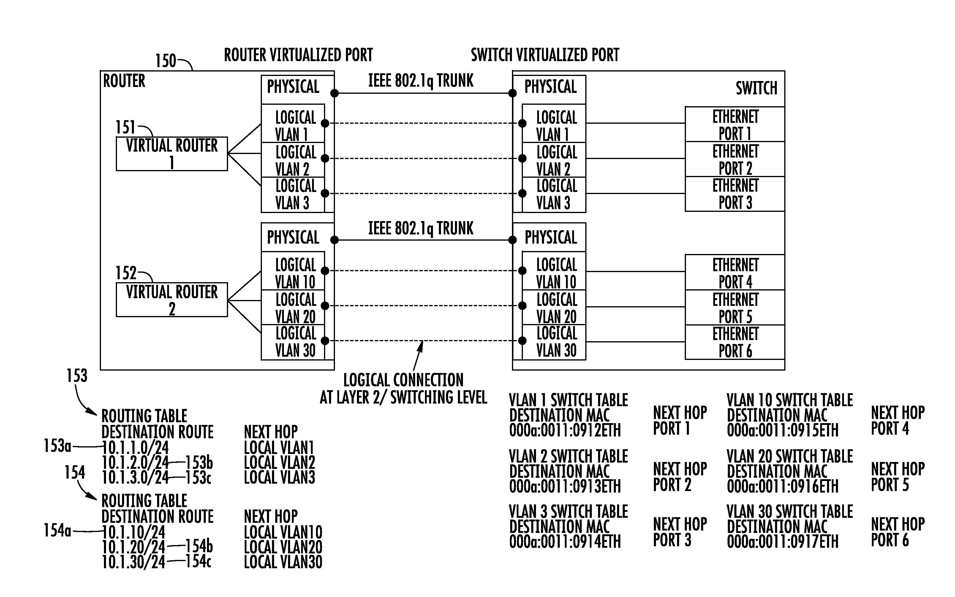
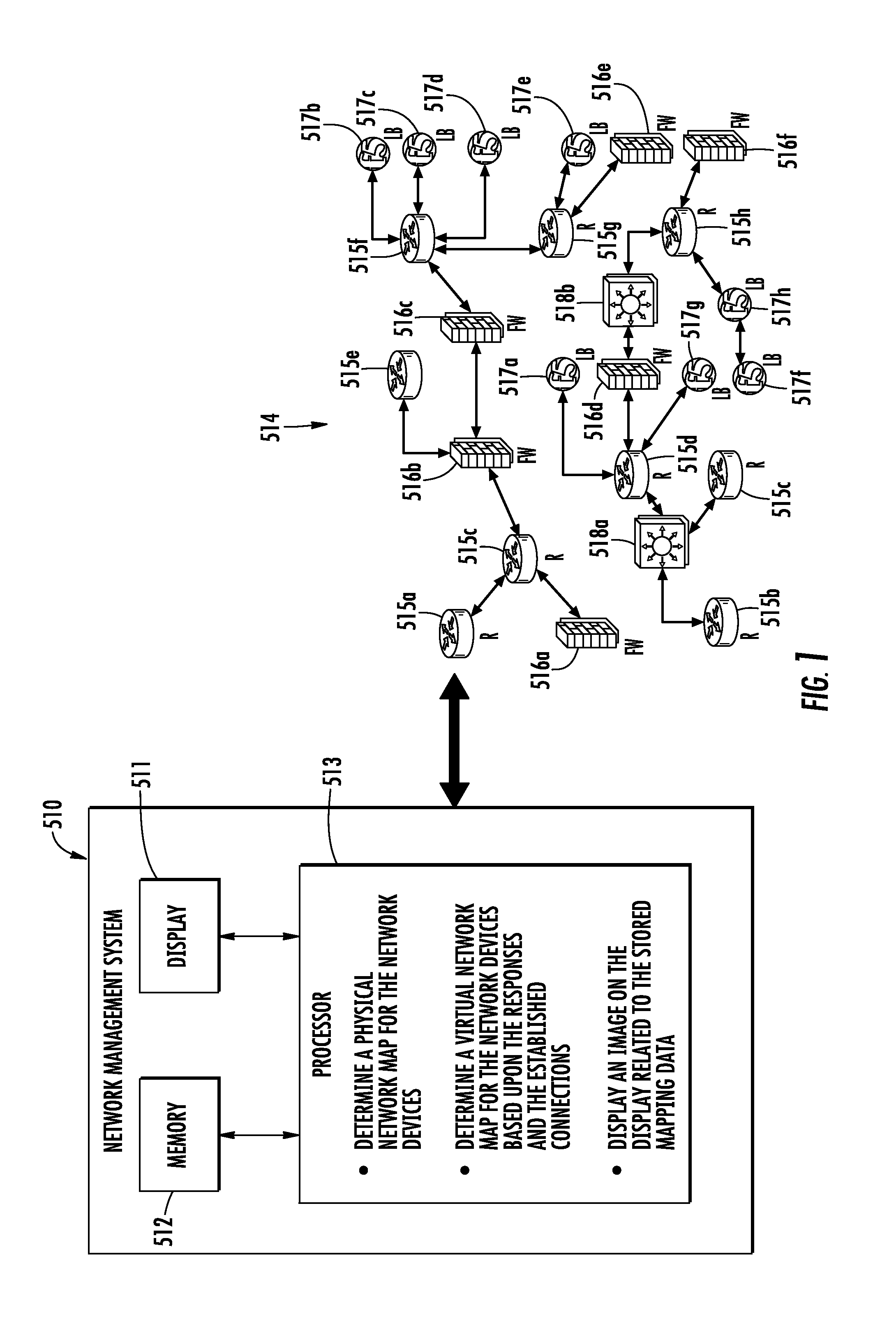
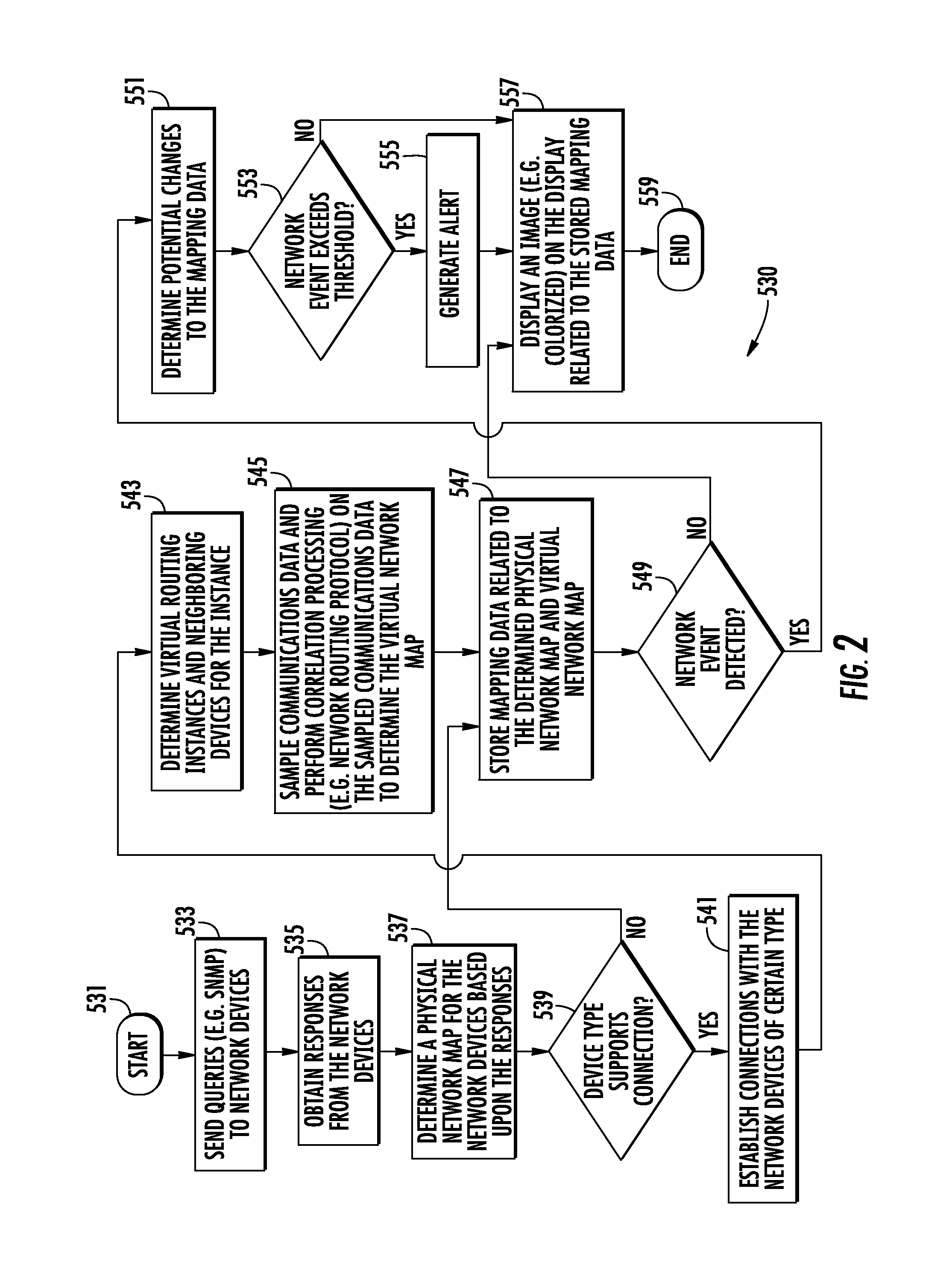
[0043]The invention provides an interface to permit an informed user to define the physical and logical extent and features of a network including a level of confidence about the information supplied. Also provided is an exhaustive query of physical and logical components of network devices on a network of defined scope using the input from the user interface and applying a logical model to ascertain the scope of the network. The physical and logical compo...


PUM


Abstract

A network management system is for a network having network devices. The network management system includes a display, a memory, and a processor coupled to the display and memory and configured to send queries to the network devices, obtain responses from the network devices based upon the queries, and determine a physical network map for the network devices based upon the responses. The processor is also configured to establish connections with some of the network devices, determine a virtual network map for the network devices based upon the responses and the established connections, store mapping data related to the determined physical network map and virtual network map in the memory, and display an image on the display related to the stored mapping data.

Description

GOVERNMENT RIGHTS[0001]This invention was made with U.S. government support under Government Contract No. DG133-E-09-CN-0094. The U.S. Government has certain rights in this invention.FIELD OF THE INVENTION[0002]The present invention relates to the field of computer networking, and, more particularly, to devices for mapping networks and related methods.BACKGROUND OF THE INVENTION[0003]Since the 1970's and the creation of ARPANET, the first modern network and predecessor of the Internet, computer interconnectivity or networking has been a typical functionality for host computing devices. With the genesis of the Internet came a clear understanding of the networking of host compute devices, network switch / hubs and network router / gateways. Early network routing devices (originally termed gateways or hubs) utilized single non-virtualized instances of Gateway-to-Gateway Protocol and Exterior Gateway Protocol created by Bold, Beranek and Newman (BBN). The first known logical map of an IP ne...

Claims


Application Information

Patent Timeline
Patent Type & Authority Applications(United States)
IPC IPC(8): H04L12/24H04L12/713H04L45/586
CPCH04L45/586H04L41/12H04L12/4641H04L41/122
Inventor BARDGETT, JAMES A.MIGUEZ, MARCUS ALEXANDERWIERZBOWSKI, PAUL
Owner HARRIS CORP
Why Eureka
Try Eureka