Image guided implantology methods

a technology of image guided implantology and image correction, which is applied in the field of correction of scanned images of, can solve the problems of ct scanner data being distorted, damage to adjacent teeth, and possible perforation of cortical plates, and achieve the effect of accurate positional data

Inactive Publication Date: 2008-11-25
IMAGE NAVIGATION LTD
View PDF15 Cites 81 Cited by
  • Summary
  • Abstract
  • Description
  • Claims
  • Application Information

AI Technical Summary

Benefits of technology

[0009]The present invention seeks to provide new methods for ensuring the accurate use of CT or MRI scanned images in surgical procedures, such as image-guided implantology. There is thus provided according to a first preferred embodiment of the present invention, a method whereby inherent distortions in the CT or MRI imaging process, or distortions arising from excessive patient movement during the scan are corrected by means of a registration device inserted into the mouth of the patient at the time the scan is being performed. To this registration device is attached in a reproducible manner, a device known as a distortion body which contains a set of fiducial markers disposed in a predetermined three-dimensional pattern, and whose location is registered on the images during the scanning. The exact positions of the fiducial markers are known with respect to each other, thus providing a three-dimensional reference against which the resulting images can be compared. This provides accurate spatial position information for correcting any distortion present in the scanning and image-processing procedure. Calculations are then performed for determining the exact location of the fiducials in the CT data, the distortion between the three dimensional image obtained and the known true location of the fiducials, and for producing a correction function for use in interpreting the CT or MRI data such that it provides accurate positional data.
[0011]These images are then spatially and angularly related to the pre-operative images by means of a pre-registration procedure performed according to another preferred embodiment of the present invention, in which a registration body containing fiduciary markers is inserted in a predefined manner into a registration jig, prior to commencement of any work on the patient. The position of the jig together with the inserted registration body is tracked by the tracking system preferably by means of LED's mounted on the jig. Alternatively and preferably, the position of the registration body can be made known to the tracking system by any other suitable positional determining device, such as by a manually held stylus which is touched onto a reference point of the registration body, or even onto the fiducial markers themselves. Since the fiducial markers are the same ones as were incorporated in the scans previously made with the registration body in the patient's mouth, and thus bear a predefined and fixed spatial and angular relationship to the registration body, and the registration body to the patient's teeth, this correlation enables the virtual-world CT scans to be related to the functional world of the tooth and drill as tracked in real time by the system. Since this registration procedure is performed outside of the patient's mouth, it has a number of advantages over prior art registration procedures performed involving the patient's jaw. In the first place, since the registration procedure is performed outside of the patient's mouth, and without patient involvement, the accuracy and the reliability of the registration process is increased, as is the patient comfort level, for the reasons stated hereinabove. Secondly, the registration process can be performed at any time before the procedure on the patient, and requires less skill and time than an intra-oral registration procedure, as in the prior art, with all the advantages thereby engendered.
[0013]There is also provided in accordance with another preferred embodiment of the present invention, a a method of compensating for distortions generated in an imaging process, comprising the steps of (a) providing a registration device with a plurality of markers disposed in a predetermined three-dimensional pattern, the markers being rendered visible in the imaging process, (b) producing a scanned image of an object of interest in the presence of the registration device, and (c) correcting the data of the scanned image such that the image of the markers accurately reproduces the predetermined three-dimensional pattern. The plurality of markers are preferably disposed either within the registration device, or within a body attached to the registration device. The above-described method can preferably be used for computerized tomography or for MRI imaging. Furthermore, the method can preferably be used when the object is at least part of a jaw of a subject, in which case the registration device is adapted to fit in a reproducible position in the at least part of the jaw.

Problems solved by technology

Examples of such potential damage include inadvertent entry into the mandibular nerve canal, possible perforation of the cortical plates, or damage to adjacent teeth.
Such data as supplied by the CT scanner may generally be distorted, whether because of imperfections in the algorithms used in the scanner software, or because of interpolations made in areas where exact measurements are not performed, or simply because of inaccuracies due to excessive patient movement during the CT scan.
Very high accuracy is required in dental implantology, where even a fraction of a millimeter of excess penetration or a degree or two of misalignment, can mean the difference between a successful procedure and an unsatisfactory one, or even between a safe procedure and injury to the patient.
Consequently, the distortion inherent in generally available CT scans is such that such scans cannot be used as supplied, for accurate image-guided dental implantology.
Without such correlation, even the most accurate and undistorted CT scan is of very limited use for guiding any sort of real time surgical procedure, such as implant preparation.
Such a referencing method may be considered disadvantageous since it entails subject involvement, and may also be dependent on operator skill in attachment of the 3-D sensor to the outside of the patient's jaw.
Furthermore, physiological changes taking place in the tissue and muscle of the patient's jaw during the course of the procedure may induce inaccuracies in the position of the sensor.
These factors may compromise the high accuracy required for an accurate implant procedure.

Method used


Image

  • Image guided implantology methods
  • Image guided implantology methods
  • Image guided implantology methods

Examples


Embodiment Construction

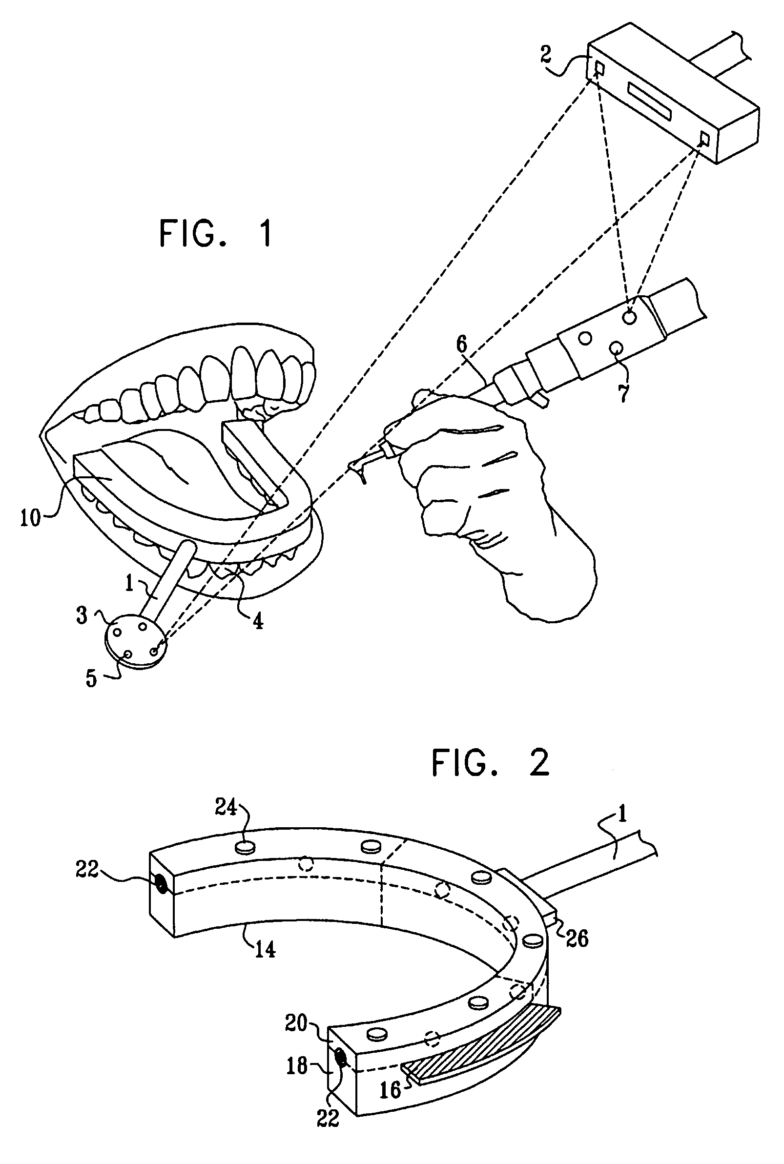
[0034]Reference is now made to FIG. 1, which illustrates schematically some of the parts of a system for performing image guided implantology, to illustrate the utilization of preferred methods and devices of the present invention. The teeth of the lower jaw 4 of a patient are shown, with a registration device 10 preferably having a horseshoe shape and adapted so that it sits comfortably in the mouth of the subject in a defined position relative to the subject's teeth. For clarity, the jaw is shown open in FIG. 1, but during the scanning process, the mouth would generally be closed to grip the registration device. Furthermore, although the complete registration device is shown in FIG. 1, in practice, when tracking is needed during a dental procedure, only part of the registration device would be left in the patient's mouth, to provide clear access to the tooth to be worked on, as explained hereinbelow. To the registration device is preferably attached, by means of a connection rod 1...


PUM


Abstract

A method for correcting inherent distortions in a CT or MRI imaging process, or distortions arising from excessive patient movement during the scan by means of a registration device inserted into the mouth of the patient at the time the scan is being performed. The registration device incorporates a set of fiducial markers disposed in a predetermined three-dimensional pattern. The exact positions of the fiducial markers are known with respect to each other, thus providing a three-dimensional reference against which the resulting images can be compared. Additionally, a method whereby three-dimensional CT or MRI images taken prior to an operation, are accurately registered and integrated with real-time tracking positional data of the patient's body part and instruments operating thereon. Application is described for the drilling of a patient's jaw for the placement of dental implants.

Description

FIELD OF THE INVENTION[0001]The present invention relates to the field of the correction of scanned images of an object and the relation of these images to the actual real-life position of the object, and especially as applied to CT images of a subject's teeth and the relation of these CT images to the actual teeth in the subject's jaw, as used in the preparation of drilled cores for the placement of dental implants.BACKGROUND OF THE INVENTION[0002]The use of threaded inserts, generally made of titanium, has become the dominant technology currently used for dental implant surgery. Such inserts must be precisely located in the tooth in order to provide optimum aesthetic and beneficial results. Bone preparation must be precise and should preferably be carried out with the implant site and shape in constant view of the dental surgeon. In particular, during the drilling phase of the bone preparation, great care must be taken to avoid causing injury to the patient. Examples of such poten...

Claims


Application Information

Patent Timeline
Patent Type & Authority Patents(United States)
IPC IPC(8): G06K9/00A61BG01R33/32A61B1/00A61B5/055A61B6/03A61B6/14A61C1/08A61C19/04
CPCA61B6/14A61C1/084G06T7/0028Y10S128/922A61C9/0093G06T7/33
Inventor PERSKY, NATHAN
Owner IMAGE NAVIGATION LTD
Why Eureka
Try Eureka