Display panel and display device

A technology for display panels and display devices, applied in nonlinear optics, instruments, optics, etc., can solve problems such as increasing the step width of display panels

Active Publication Date: 2019-04-16
XIAMEN TIANMA MICRO ELECTRONICS
View PDF13 Cites 14 Cited by
  • Summary
  • Abstract
  • Description
  • Claims
  • Application Information

AI Technical Summary

Problems solved by technology

[0003] In existing COG products, the signal lines in the display area are electrically connected to the terminals (pads) of the integrated circuit binding area through fan-out routing. The area between the display area and the integrated circuit binding area is called the fan-out area. The fan-out traces in the out-of-area are distributed in an inverted trapezoida

Method used


Image

  • Display panel and display device
  • Display panel and display device
  • Display panel and display device

Examples


Embodiment Construction

[0058] In order to better understand the technical solutions provided by the embodiments of the present application, a detailed description will be given below in conjunction with the accompanying drawings and specific implementation manners.

[0059] In order to facilitate a better understanding of the technical solution of the present application, the prior art involved in the present application will first be described below.

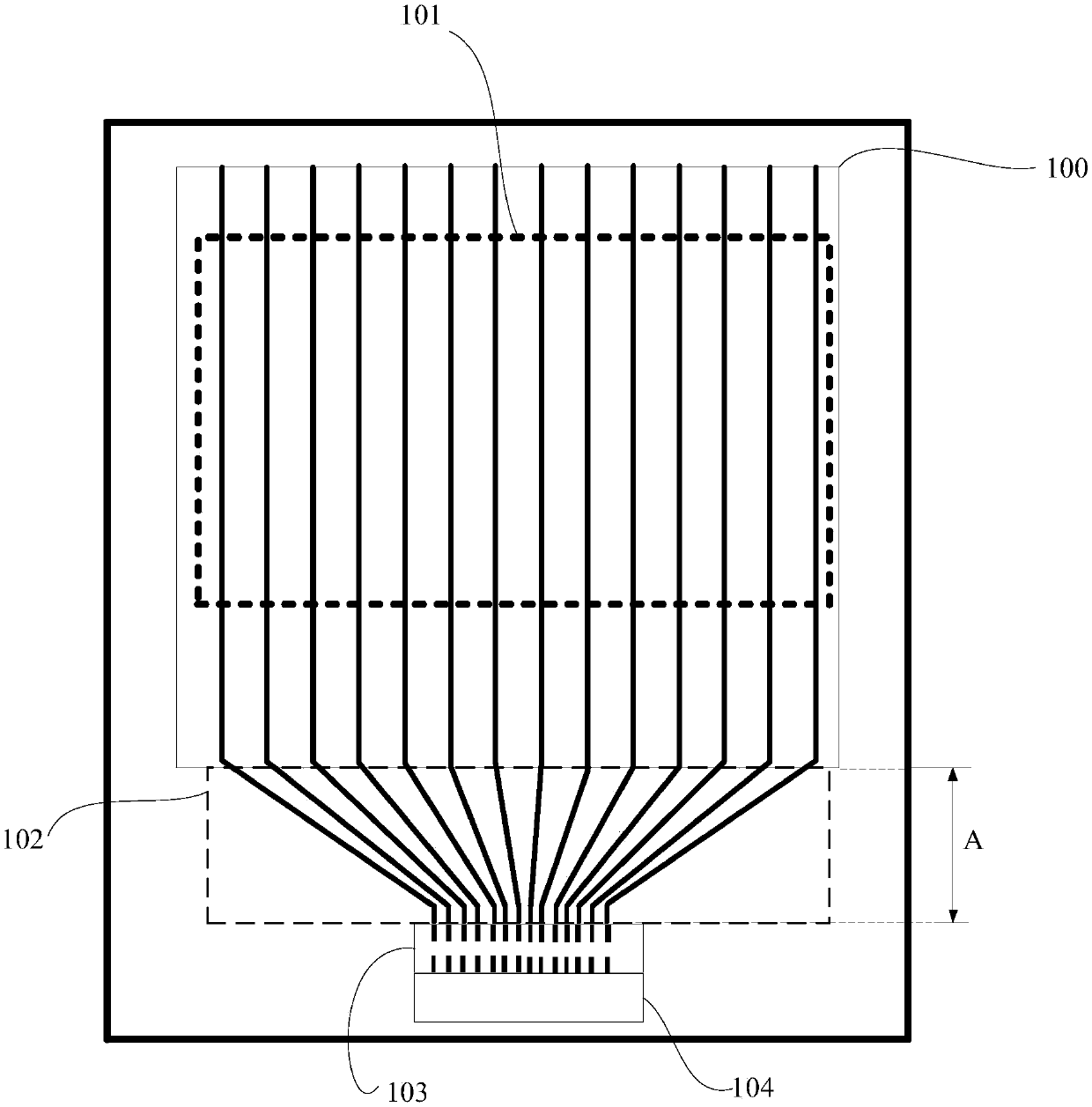
[0060] Please refer to figure 1 , figure 1 It is a structural schematic diagram of a display panel in the prior art. The display panel includes a display area 100, signal lines ( figure 1 The signal line in the display area 100 is represented by reference numeral 101 in the display area 100 ). The signal line 101 and the fan-out routing ( figure 1 The reference number 102 is used in the display area 100 to indicate that one end of the fan-out wiring) is electrically connected, and the other end of the fan-out wiring 102 is electrically connected ...


PUM


Abstract

The invention provides a display panel and a display device to reduce the step width of the display panel. The display panel comprises a display area, a non-display area which comprises an integratedcircuit binding area and a fan-out area, signal lines which comprise first and second signal lines in the display area, and fan-out traces which comprise a first fan-out trace and a second fan-out trace. The first fan-out trace and the second fan-out trace are both located in the fan-out area. The first fan-out trace is electrically connected with the first signal line. The second fan-out trace iselectrically connected with the second signal line. The first fan-out trace is electrically connected with a first terminal of an integrated circuit binding area through a first side. The second fan-out trace is electrically connected with a second terminal of the integrated circuit binding area through a second side. The first side and the second side are two different sides in the integrated circuit binding area.

Description

technical field [0001] The present application relates to the field of display technology, in particular to a display panel and a display device. Background technique [0002] When making a liquid crystal display (Liquid Crystal Display, LCD), it is usually packaged by Chip On Glass (COG) technology, and the displays packaged by the COG technology are collectively referred to as COG products. [0003] In existing COG products, the signal lines in the display area are electrically connected to the terminals (pads) of the integrated circuit binding area through fan-out routing. The area between the display area and the integrated circuit binding area is called the fan-out area. The fan-out traces in the out-of-area are distributed in an inverted trapezoidal shape, resulting in a wider line width of the traces between the integrated circuit bonding area and the signal lines in the display area. In this way, a sufficient distance needs to be left between the integrated circuit ...

Claims


Application Information

Patent Timeline
IPC IPC(8): G02F1/1345
CPCG02F1/1345G02F1/13452G02F1/13456
Inventor 孟垂玉周秀峰伍黄尧沈柏平
Owner XIAMEN TIANMA MICRO ELECTRONICS
Why Eureka
Try Eureka