
A low temperature coefficient step-up circuit with adjustable amplitude

A low temperature coefficient, boost circuit technology, applied in the direction of adjusting electrical variables, control/regulation systems, instruments, etc., can solve the problems of difficult to turn off the boost function, consume large power consumption, and difficult to change the boost range, etc., to achieve output The effect of high voltage precision, satisfying current precision, and high accuracy

Active Publication Date: 2019-10-15
SOUTH CHINA UNIV OF TECH
View PDF3 Cites 0 Cited by
  • Summary
  • Abstract
  • Description
  • Claims
  • Application Information

AI Technical Summary

Problems solved by technology

[0004] The commonly used equal-amplitude boost method is diode boost. The boost is achieved by connecting diodes in series with the input signal. The boost range of this boost method is controlled by the number of diodes. It is difficult to change the boost range after confirmation, and it is difficult to turn off the boost function. ; Directly adopting the method of resistive voltage division will consume a lot of power consumption, especially when dealing with negative voltage; using a stable current source and boosting resistor to boost the voltage will cause the boosting range due to the temperature coefficient of the resistor and process deviation It also changes with temperature and process changes, and the boost range is uncontrollable; the boost conversion circuit using MOS tube input cannot be used for negative voltage boost; and the charge pump and boost boost circuits not only output a fixed range of voltage , and cannot be applied to negative input voltage

Method used


Image

  • A low temperature coefficient step-up circuit with adjustable amplitude
  • A low temperature coefficient step-up circuit with adjustable amplitude
  • A low temperature coefficient step-up circuit with adjustable amplitude

Examples


Embodiment Construction

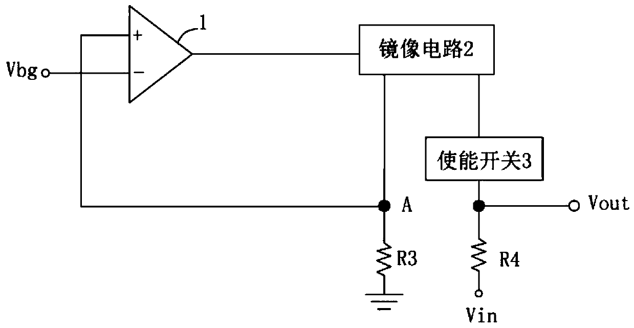
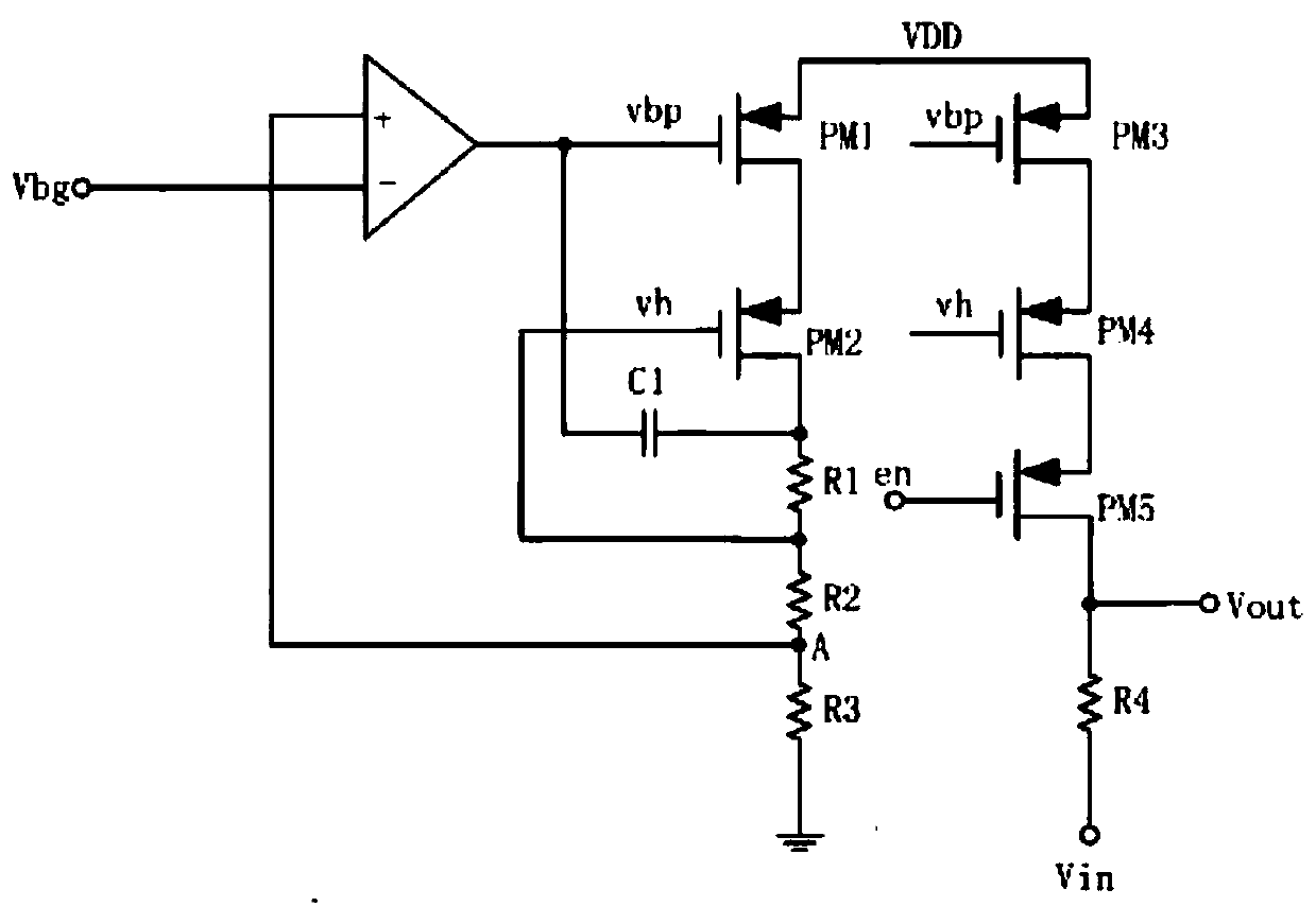
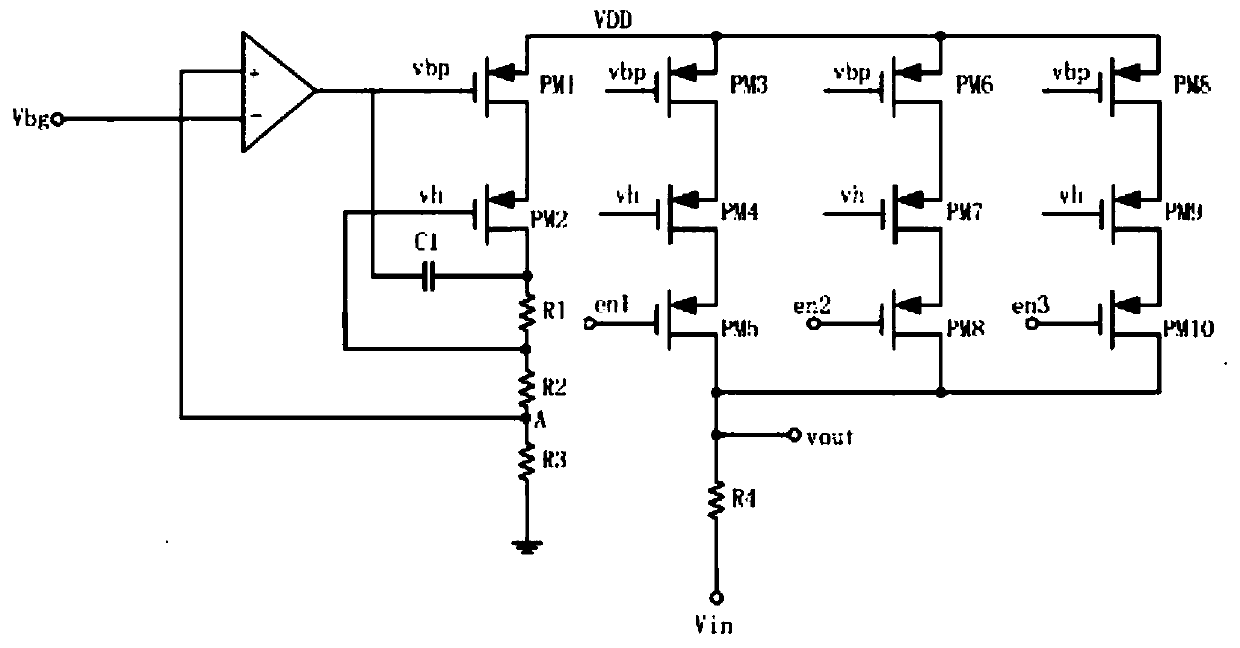
[0021] like figure 1 , figure 2 As shown, an amplitude-adjustable low temperature coefficient step-up circuit according to the present invention includes an operational amplifier 1, a mirror circuit 2 containing an op-amp negative feedback loop, a sampling resistor R3, a boosting resistor R4 and an enabling switch 3 ; The inverting input terminal of the operational amplifier 1 is used to input a reference voltage, and the non-inverting input terminal of the operational amplifier 1 is connected to the sampling resistor R3 and then grounded; the input terminal of the mirror circuit 2 is connected to the output of the operational amplifier 1 end, the first output end of the mirror circuit 2 is connected to the sampling resistor R3 and then grounded, and the second output end of the mirror circuit 2 is connected to the boost resistor R4 after the enabling switch 3; the negative feedback of the operational amplifier The loop is used to make the voltage between the mirror circuit ...


PUM


Abstract

The invention discloses a low-temperature coefficient boosting circuit with adjustable amplitude. The low-temperature coefficient boosting circuit comprises an operational amplifier, a mirror image circuit containing an operational amplifier negative feedback loop, a sampling resistor, a boosting resistor and an enabling switch; the inverting input end of the operational amplifier is used for inputting reference voltage, and the same-phase input end of the operational amplifier is connected with the sampling resistor and then is grounded; the input end of the mirror image circuit is connectedwith the output end of the operational amplifier, the first output end of the mirror image circuit is connected with the sampling resistor and then is grounded, and the second output end of the mirrorimage circuit is connected with the boosting resistor after passing through the enabling switch; the negative feedback loop of the operational amplifier is used for enabling the voltage between the mirror image circuit and the sampling resistor to be equal to the reference voltage; and a voltage output end is arranged between the enabling switch and the boosting resistor, and the sampling resistor and the boosting resistor are the same in type. The low-temperature coefficient boosting circuit has the characteristics of being adjustable in amplitude, low in temperature coefficient and precision and the like.

Description

technical field [0001] The invention relates to the field of semiconductor integrated circuits, in particular to a voltage boosting circuit with adjustable amplitude and low temperature coefficient. Background technique [0002] In the processing of voltage signals, weak low-voltage signals or negative voltage signals are often encountered, especially for negative voltage signals, which cannot be directly applied to subsequent positive power supply voltage processing circuits such as comparators; therefore, low-voltage signals or negative voltage signals need to be processed The negative voltage signal is boosted to facilitate subsequent signal processing. [0003] For signals that are particularly important for such amplitude characteristics, the amplitude characteristics of the signal should be preserved while boosting. Therefore, it is not possible to do a fixed output boost for this type of signal, but to use an equal-amplitude boost method to retain the amplitude chara...

Claims


Application Information

Patent Timeline
Patent Type & Authority Patents(China)
IPC IPC(8): G05F1/56
Inventor 李斌陈鸿陈志坚郑彦祺黄沫周绍林
Owner SOUTH CHINA UNIV OF TECH
Learn More