RF antenna with protection structure

A technology for protecting structures and antennas, applied in the field of RF antennas, can solve problems such as inconvenient installation and maintenance, and achieve the effect of convenient alignment and time saving

Inactive Publication Date: 2019-04-16
徐州星耀电子有限公司
View PDF0 Cites 0 Cited by
  • Summary
  • Abstract
  • Description
  • Claims
  • Application Information

AI Technical Summary

Problems solved by technology

[0004] The purpose of the present invention is to solve the disadvantages of inconvenient installation and maintenance in the prior art, and propose a RF antenna with a protective structure

Method used


Image

  • RF antenna with protection structure
  • RF antenna with protection structure
  • RF antenna with protection structure

Examples


Embodiment Construction

[0017] The technical solutions in the embodiments of the present invention will be clearly and completely described below in conjunction with the accompanying drawings in the embodiments of the present invention. Obviously, the described embodiments are only a part of the embodiments of the present invention, rather than all the embodiments.

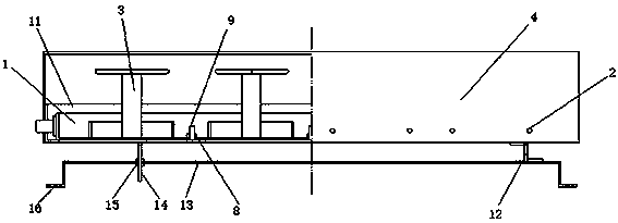
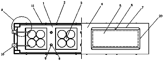
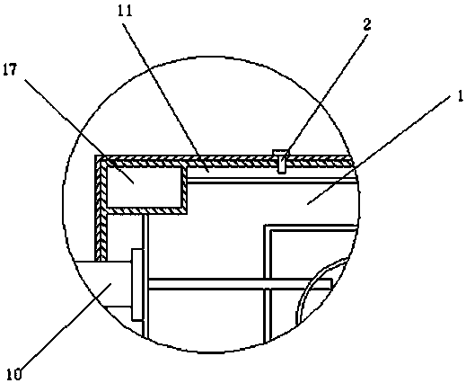
[0018] Reference Figure 1-4 , An RF antenna with a protective structure, including a reflector 1 on which a plurality of vibrators 3 and terminals 10 are provided, and the terminals 10 are connected to the vibrator 3 through a feeder, and also include a box-like shield with an open top Shell 11, the reflecting plate 1 is detachably fixed in the protective shell 11, the reflecting plate 1 is provided with a plurality of through holes, and studs 8 are inserted in the through holes, and the studs 8 are vertically fixed at the bottom of the protective shell 11. A nut 9 is screwed on the stud 8. The reflector 1 is rectangular and has rectangul...


PUM


Abstract

The invention relates to the technical field of the antenna, especially a RF antenna with a protection structure. The RF antenna comprises a reflective plate, multiple vibrators and wiring terminals are arranged on the reflective plate; the wiring terminals are connected with the vibrators through feeder lines; the RF antenna further comprises a box body protective shell with an opening at the top; the reflective plate is detachably fixed in the protective shell; an outer cover matched with the shape of the protective shell is covered at an upper part of the protective shell; the bottom edge of the outer cover is connected with the sidewall of the protective shell through multiple first connecting bolts; multiple sight openings are arranged on the top of the outer cover; sealing plates inparallel are arranged on the outer covers at two sides of the sight openings. The protective cover part is split into the protective shell and the outer cover; the protective shell and the outer coverare in a butt-joint way; the sight opening for overhauling is arranged on the outer cover; and the cover plate is arranged on the sight opening, thereby facilitating the mounting and the maintaining.

Description

Technical field [0001] The present invention relates to the field of antenna technology, in particular to an RF antenna with a protective structure. Background technique [0002] The antenna is a kind of converter that transforms the guided wave propagating on the transmission line into an electromagnetic wave propagating in an unbounded medium (usually free space), or vice versa. A component used in radio equipment to transmit or receive electromagnetic waves. Engineering systems such as radio communication, broadcasting, television, radar, navigation, electronic countermeasures, remote sensing, radio astronomy, etc., which use electromagnetic waves to transmit information rely on antennas to work. [0003] The structure of the communication base station antenna in the prior art includes a reflector, a vibrator, a radome, and a feeding network. The radome is a rectangular tube with open ends. After the internal components are installed, the two ends are sealed and installed. It ...

Claims


Application Information

Patent Timeline
Patent Type & Authority Applications(China)
IPC IPC(8): H01Q1/42H01Q1/50H01Q15/14
CPCH01Q1/42H01Q1/50H01Q15/14
Inventor 张明李敬宜
Owner 徐州星耀电子有限公司
Why Eureka
Try Eureka