Crown spring mounting structure with good restriction and convenient disassembly

A technology of installation structure and crown spring, which is applied in the direction of coupling device, parts of connection device, fixed/insulation contact components, etc., can solve the difficulty of disassembling the connection structure of crown spring and sleeve, the easy axial displacement of crown spring and the Circumferential displacement, axial displacement and circumferential displacement and other issues, to achieve the effect of carrying current, easy to generate heat, and large impedance

Inactive Publication Date: 2019-04-16
JIANGSU WANBANG DEHE NEW ENERGY TECH CO LTD
View PDF5 Cites 3 Cited by
  • Summary
  • Abstract
  • Description
  • Claims
  • Application Information

AI Technical Summary

Problems solved by technology

[0005] The purpose of the present invention is to overcome the existing technology that the crown spring is prone to axial displacement and circumferential displacement in the sleeve, which is not convenient for charging connection; and it is very difficult to disassemble the connection structure of the crown spring and the sleeve. The overall replacement of the connection structure, the defect of high maintenance cost for the overall replacement, provides a method that can avoid the axial displacement and circumferential displacement of th

Method used


Image

  • Crown spring mounting structure with good restriction and convenient disassembly
  • Crown spring mounting structure with good restriction and convenient disassembly
  • Crown spring mounting structure with good restriction and convenient disassembly

Examples


Embodiment 1

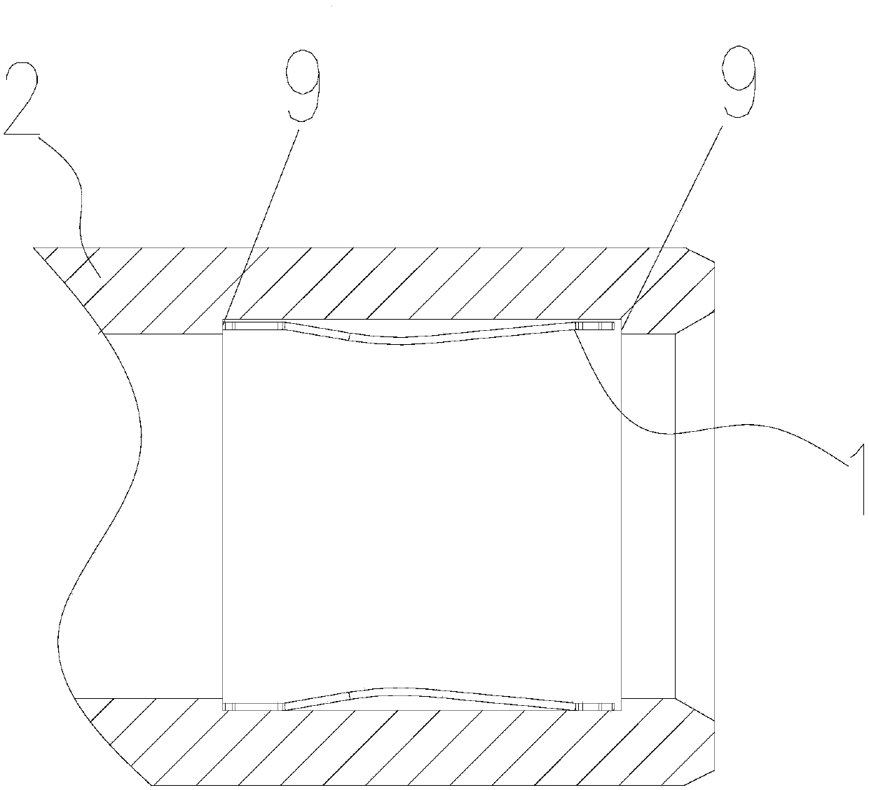
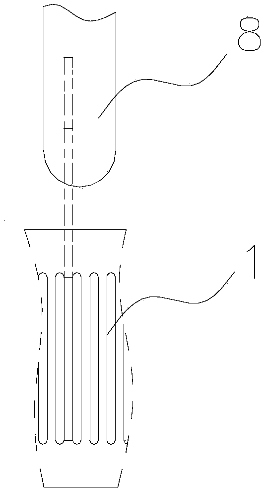
[0053] Such as Figure 4-Figure 7 The shown embodiment 1 of a crown spring installation structure with good positioning and easy disassembly of the present invention includes a crown spring 1 and a sleeve 2 sleeved on the crown spring 1, and the crown spring 1 is close to both ends. A plurality of elastic flaps 3 are evenly distributed on the outer circular surface in the circumferential direction. The elastic flaps 3 are the plate surfaces of the crown spring 1 that are turned outward. The folding plates 3 are arranged in the through holes 4 in one-to-one correspondence; the folding directions of the elastic folding plates 3 at both ends of the crown spring 1 are set in opposite directions, and the free ends of the elastic folding plates 3 are all against the holes of the through holes 4 on the wall.

[0054] When installing, press the elastic flap 3 at one end of the crown spring 1, so that the crown spring 1 is inserted into the sleeve 2, and the crown spring 1 is set in t...

Embodiment 2

[0062] Such as Figure 4 , 5 , 6, 8 and 9 show a second embodiment of a crown spring installation structure with good position-limiting and convenient disassembly of the present invention. The difference between this embodiment and the first embodiment is that the inner sleeve 2 The circular surface is provided with a first protrusion 6 in the circumferential direction, and the elastic expansion section of the reed of the crown spring 1 fits on the first protrusion 6 when it is in a tension limit state.

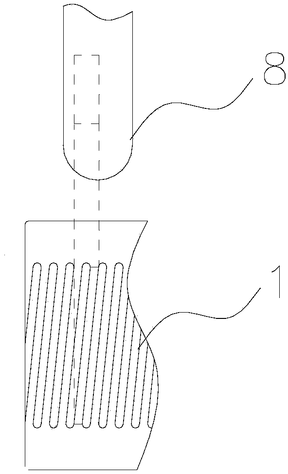
[0063] The elastic expansion section is a concave radial elastic expansion and contraction part in the middle of the reed of the crown spring 1 . After the pin 8 is inserted, in this embodiment, the reed of the crown spring 1 is under pressure, so that the reed can be directly attached to the first protrusion 6 of the sleeve 2, which shortens the transmission path of the energized current and reduces Volume resistance, reduce heat generation, increase current carrying capac...

Embodiment 3

[0070] Such as Figure 4 , 5, 6, 10 and 11 show a third embodiment of a crown spring installation structure with good position limiting and easy disassembly of the present invention. The difference between this embodiment and embodiment 1 is that each crown spring 1 The outer surface of the reed is provided with a second protrusion 7 in the shape of a boss. When the elastic relaxation section of the reed of the crown spring 1 is in the tension limit state, each second protrusion 7 is attached to the sleeve 2 on the inner wall.

[0071] The elastic expansion section is a concave radial elastic expansion and contraction part in the middle of the reed of the crown spring 1 . After the pin 8 is inserted, the second protrusion 7 on the reed of this embodiment can be directly attached to the inner wall of the sleeve 2 when the reed of the crown spring 1 is under pressure, shortening the transmission path of the energized current , Reduce volume resistance, reduce heat generation,...


PUM

PropertyMeasurementUnit
Lengthaaaaaaaaaa
Widthaaaaaaaaaa
Bending angleaaaaaaaaaa

Abstract

The invention belongs to the technical field of electric connectors and particularly relates to a crown spring mounting structure with good restriction and convenient disassembly. The crown spring mounting structure includes a crown spring and a sleeve. Elastic folding plates are uniformly distributed on the outer circumferential surfaces of the two ends of the crown spring. A plurality of throughholes are uniformly arranged on the cylinder surfaces of the two ends of the sleeve. The elastic folding plates are disposed in the through holes and have opposite folding directions. The free ends of the elastic folding plates are abutted against the walls of the through holes. The crown spring mounting structure has the beneficial effects that the axial displacement and the circumferential displacement of the crown spring in the sleeve can be avoided, the connection structure of the crown spring and the sleeve is firmly installed, which is convenient for charging connection; regardless of the diameter of the crown spring, the crown spring is convenient to disassemble and convenient to be taken out of the sleeve, thereby contributing to the maintenance of the crown spring; when the crownspring is maintained, the replacement of the connection structure of the sleeve and the crown spring can be avoided and the maintenance cost is saved.

Description

technical field [0001] The invention belongs to the technical field of electrical connectors, and in particular relates to a crown spring installation structure with good position limiting and convenient disassembly. Background technique [0002] At present, the crown spring is widely used in the mating connection between the male pin and the female pin of the electrical connector, in order to reduce the processing accuracy requirements of the male pin and the female pin, and to prevent the male pin and the female pin from being too loose or loose due to the tolerance fit connection. The phenomenon that the electrical connector is not firmly connected or is difficult to plug and unplug due to tight fit. [0003] Among them, the female pin includes such as figure 1 The assembly and connection structure of the existing sleeve 2 and crown spring 1 is shown. The crown spring 1 is in the shape of a waist drum, that is, the two ends are large and the middle is small. The crown sp...

Claims


Application Information

Patent Timeline
IPC IPC(8): H01R13/11H01R13/40
CPCH01R13/111H01R13/40
Inventor 贺云峰邵丹薇李德胜储丹杨志
Owner JIANGSU WANBANG DEHE NEW ENERGY TECH CO LTD
Why Eureka
Try Eureka