
A multi-channel debris flow impact state tracking simulation system and operation method

A technology for simulating systems and debris flow, applied in three-dimensional systems, image communications, fluid dynamics tests, etc., can solve problems such as large measurement errors and unfavorable protective measures, and achieve the effects of easy operation, good recovery of real data, and improvement of measurement accuracy

Inactive Publication Date: 2020-12-22
CHENGDU UNIVERSITY OF TECHNOLOGY
View PDF7 Cites 0 Cited by
  • Summary
  • Abstract
  • Description
  • Claims
  • Application Information

AI Technical Summary

Problems solved by technology

[0005] The invention provides a multi-channel debris flow impact state tracking simulation system and operation method, which solves the problem that the large measurement error is not conducive to better protective measures

Method used


Image

  • A multi-channel debris flow impact state tracking simulation system and operation method
  • A multi-channel debris flow impact state tracking simulation system and operation method
  • A multi-channel debris flow impact state tracking simulation system and operation method

Examples


no. 1 example

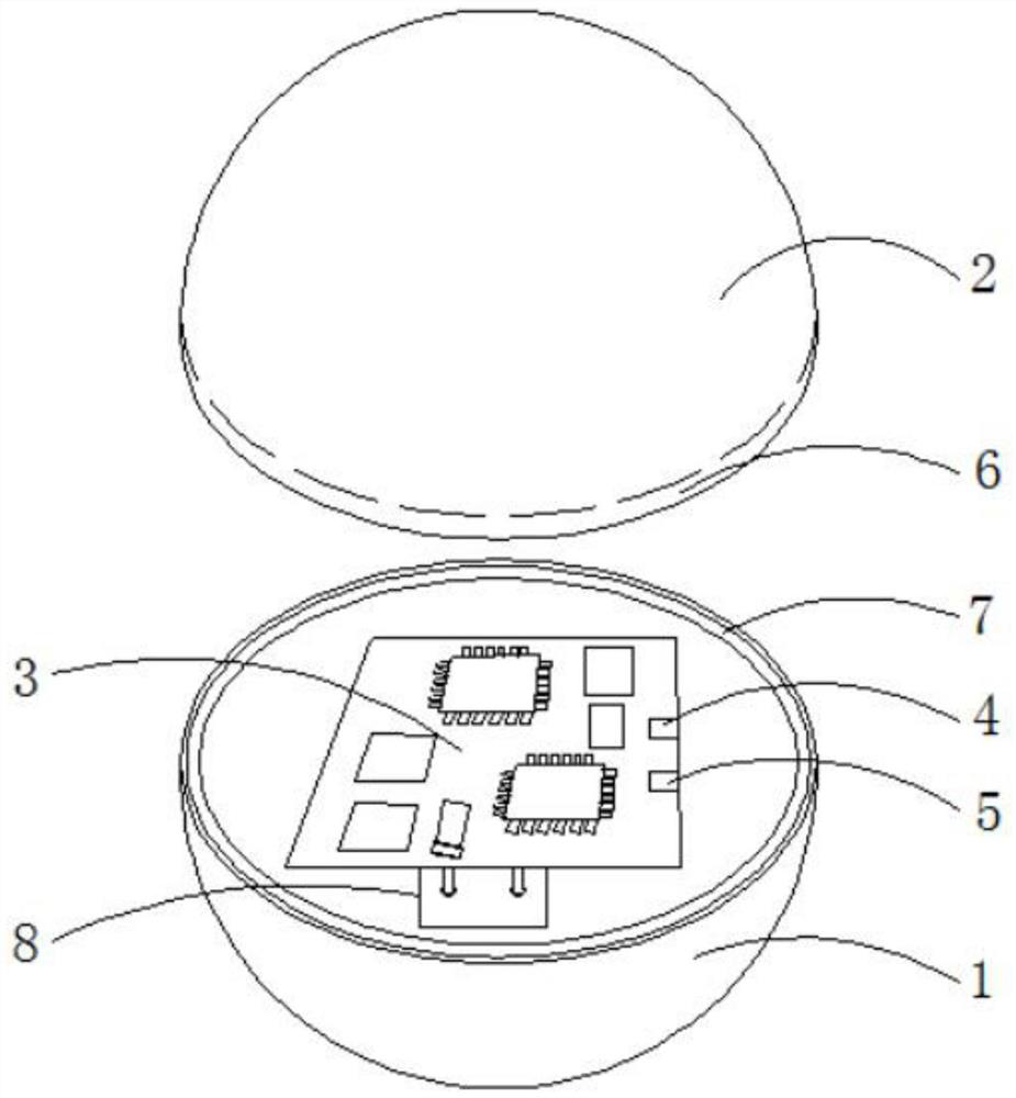
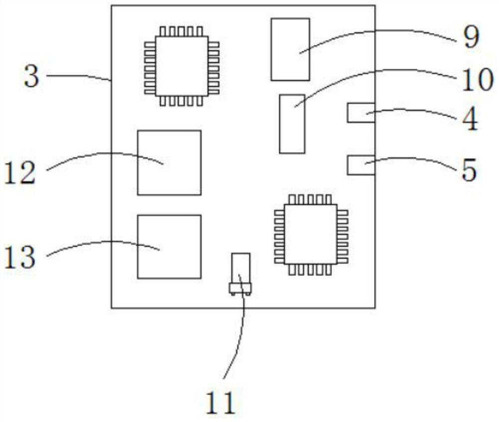
[0036]Please refer tofigure 1 ,figure 2 ,image 3 ,Figure 6 ,Figure 7 ,Figure 8 ,Picture 9 ,Picture 10 ,Picture 11 withPicture 12 ,among them,figure 1 It is a schematic structural diagram of the first embodiment of the multi-channel debris flow impact state tracking simulation system and operation method provided by the present invention;figure 2 forfigure 1 The structure diagram of the conveying structure shown;Figure 6 Acceleration and magnetometer fitting diagrams of the multi-channel debris flow impact state tracking simulation system and operation method provided by the present invention;Figure 7 The quaternion posture output data diagram of the multi-channel debris flow impact state tracking simulation system and operation method provided by the present invention;Figure 8 The human-computer interaction display-trajectory display diagram of the multi-channel debris flow impact state tracking simulation system and operation method provided by the present invention;Picture 9 The h...

no. 2 example

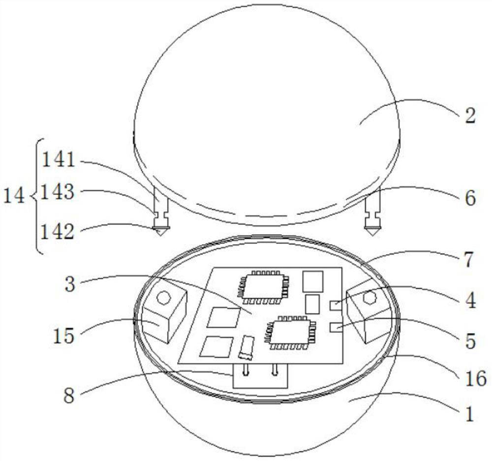
[0049]Please refer toFigure 3 to Figure 5Based on the multi-channel debris flow impact state tracking simulation system and operation method provided by the first embodiment of the present invention, the second embodiment of the present invention provides the multi-channel debris flow impact state tracking simulation system and operation method. The difference lies in that Both sides of the inner wall of the spherical cover 2 are fixedly connected with a clamping structure 14, the clamping structure 14 includes a top rod 141, the bottom end of the top rod 141 is fixedly connected with a tapered block 142, the top rod 141 Limiting slots 143 are provided on both sides, and the setting of the limiting slots 143 is mainly to facilitate the clamping of the protrusion 153.

[0050]Limiting devices 15 are provided on both sides of the inner wall of the hemisphere 1, and the limiting device 15 includes a movable box 151. Both sides of the bottom of the inner wall of the movable box 151 are sli...


PUM


Abstract

The invention provides a multi-channel debris flow impact state tracking simulation system and an operation method thereof. The multi-channel debris flow impact state tracking simulation system comprises a hemisphere, a ball cover, a main board, a data interface, and a charging interface. The hemisphere is adapted to the ball cover. An annular clamp slot is formed in the bottom of the inner surface of the ball cover; an annular clamp block is fixedly connected to the top of the inner surface of the hemisphere; and the annular clamp block and the annular clamp slot are matched. The main board is adhered to the inside of the hemisphere by glue; and the data interface is disposed at one side of the top of the main board. On the basis of a method of simulating particles, the real debris flow impact data are restored and the movement tracks and the movement states of the particles in the mud can be better obtained, so that post-stage prevention and mitigation of the debris flow disasters are realized.

Description

Technical field[0001]The invention relates to the field of geological disaster prevention and control, in particular to a multi-channel debris flow impact state tracking simulation system and an operating method.Background technique[0002]The existing debris flow state acquisition technology generally uses: laser ranging, measuring the height of the debris flow, used to determine the fluctuation of the debris flow; pressure sensor measurement, used to measure the impact force of the debris flow on the side and bottom of the ramp, and for the load-bearing and diversion The impact of measures; use lidar, grating, etc. to collect debris flow information from point cloud; use infrasound to collect debris flow movement status.[0003]The current monitoring is basically reversed by external force or external monitoring, and then the impact data of the debris flow is obtained. In this way, there will be some large errors in the overall or partial data of the debris flow. Many data are obtaine...

Claims


Application Information

Patent Timeline
Patent Type & Authority Patents(China)
IPC IPC(8): G01M10/00H04N13/30
CPCG01M10/00H04N13/30
Inventor 李孝哲张庆贤方方谷懿肖鸿飞
Owner CHENGDU UNIVERSITY OF TECHNOLOGY
Learn More