Inverted roller screw reduction gear

A technology of reducer and nut, which is applied in the direction of gear transmission, belt/chain/gear, program control manipulator, etc., which can solve the problems of occupation and inability to be used as output components, etc.

Active Publication Date: 2019-04-16
戴克特股份公司
View PDF6 Cites 0 Cited by
  • Summary
  • Abstract
  • Description
  • Claims
  • Application Information

AI Technical Summary

Problems solved by technology

Due to the fact that the space inside the output member is occupied by other reducer elements, the arrangement disclosed in EA 201500520 cannot be used as a structure with an output member providing a coaxial coupling of the reciprocating mechanism

Method used


Image

  • Inverted roller screw reduction gear
  • Inverted roller screw reduction gear
  • Inverted roller screw reduction gear

Examples


Embodiment Construction

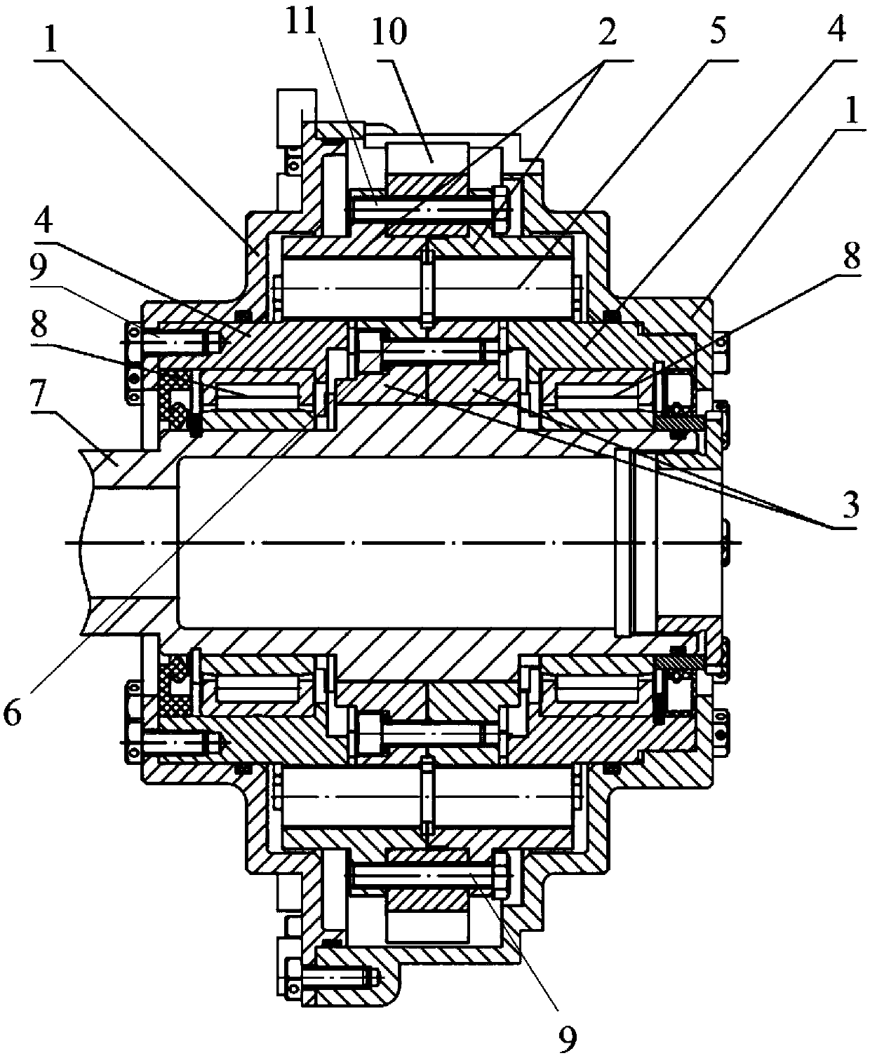
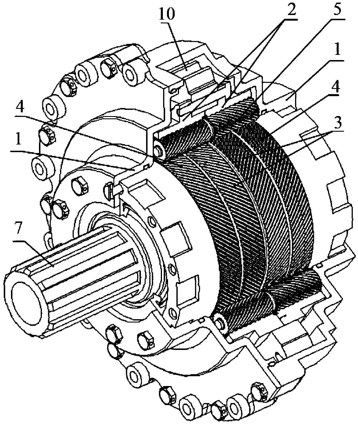
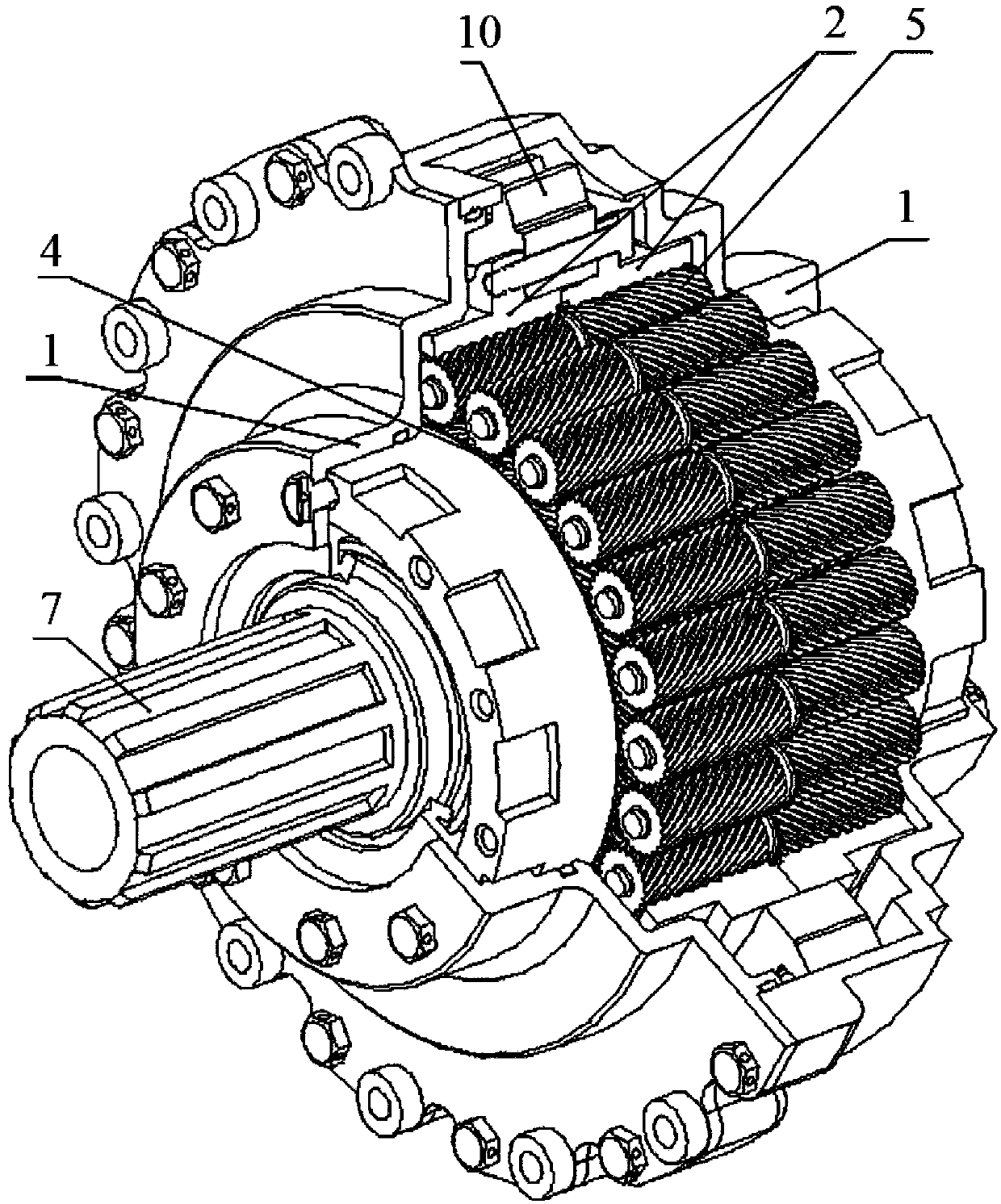
[0032] exist figure 1 In one embodiment shown, a roller reducer comprises a main body 1 receiving a reducer input member, an output member, a support member and a roller 5 . The input member includes two input member nuts 2 . The output member includes two output member nuts 3 . The support member comprises two support member nuts 4 .

[0033] Although the illustrated roller reducer includes two input member nuts 2, two output member nuts 3 and two support member nuts 4, the invention is not limited to the illustrated embodiment and the roller reducer may include more Various types of nuts.

[0034] The two output member nuts 3 cannot be displaced axially, since they are fixedly mounted relative to each other by means of a fixing member, for example by a threaded rod 6 inserted into a dedicated groove in the nut 3 . In order to prevent angular displacement of the nuts 3 relative to each other, the nuts may be connected by a spline joint (not shown).

[0035] Alternatively...


PUM


Abstract

The invention relates to the field of mechanical engineering, and more specifically to roller screw reduction gears. A roller screw reduction gear contains an input link, a support link, an output link and rollers. The rollers have at least one pair of regions having differently-directed threads. Each link contains at least two nuts which have differently-directed multi-start threads and which areaffixed relative to one another. The multi-start thread of the support link nuts and of the output link nuts is provided on the outer surface thereof. Each roller region of the at least one pair of roller regions interacts with at least one support link nut and / or at least one output link nut. At least two input link nuts are disposed around the rollers in such a way that at least one pair of roller regions interacts with the thread on the input link nuts.

Description

technical field [0001] The invention relates to planetary mechanisms for transmitting rotary motion. In particular, the invention relates to planetary reducers with stepped threaded rollers. More particularly, the present invention relates to roller reducers. Background technique [0002] The roller reducer (PBP) is a sub-equipment of the planetary reducer and can be used to adjust the torque. Roller reducers are used in manipulators, manipulators and power drives for transmissions requiring high torque within size constraints. Advantageously, the roller reducer has a simple design and few parts; provides high motion precision provided by short kinematic chains and many contact points; provides smooth and low-noise operation; has small dimensions while providing high transmitted torque; Capable of operating at high input shaft rotational speeds. [0003] EA 201500520 discloses a roller reducer, which is considered prior art for the present invention, and which comprises:...

Claims


Application Information

Patent Timeline
Patent Type & Authority Applications(China)
IPC IPC(8): F16H1/28
CPCF16H25/2252B25J9/102F16H25/04F16H1/28
Inventor 米哈伊尔·维根伊维奇·费多索夫斯基瓦季姆·伊戈列维奇·杜娜维罗曼·弗拉季米罗维奇·普斯托谢罗夫
Owner 戴克特股份公司
Why Eureka
Try Eureka