Roller Screw System

a technology of roller screws and rollers, which is applied in the direction of gearing, gearing elements, hoisting equipment, etc., can solve the problems of increasing and achieve the effect of reducing the size of the nut and circling more smoothly

Inactive Publication Date: 2008-05-15
HIWIN TECH
View PDF5 Cites 18 Cited by
  • Summary
  • Abstract
  • Description
  • Claims
  • Application Information

AI Technical Summary

Benefits of technology

[0011]The primary objective of the present invention is to provide a roller screw system that can enable the rollers to circulate more smoothly while reducing the size of the nut.
[0012]To obtain the abovementioned objective, the roller screw system in accordance with the present invention comprises a screw shaft, a nut, a pair of return members, a return pipe and a plurality of rollers. The nut is interiorly defined with a receiving recess for accommodation of the return members, and an abutting surface. The roller screw system is characterized in that a through hole is defined in the nut and is in communication with the return hole. The return pipe is disposed in the through hole of the nut. The return members are disposed in the receiving groove of the nut, forming a return system. And the return system is to be connected to the helical groove of the screw shaft and the nut, thus forming a roller screw system. By such arrangements, the present invention can solve the problems of the conventional roller screw, such as the turning radius is too small and leads to an unsmooth circulation of the roller, or the return pipe increases the size of the nut.

Problems solved by technology

However, it must use the outer circulation type roller screw when the load to be loaded is comparatively large.
Firstly, in addition to the fact that the return pipe 8 is difficult to shape and manufacture, the size of the nut will also be increased by the installation of the return pipe 8.

Method used


Image

  • Roller Screw System
  • Roller Screw System
  • Roller Screw System

Examples


Embodiment Construction

[0019]The present invention will be more clear from the following description when viewed together with the accompanying drawings, which show, for purpose of illustrations only, the preferred embodiment in accordance with the present invention.

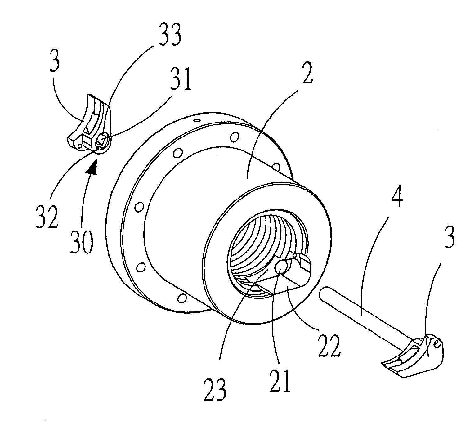
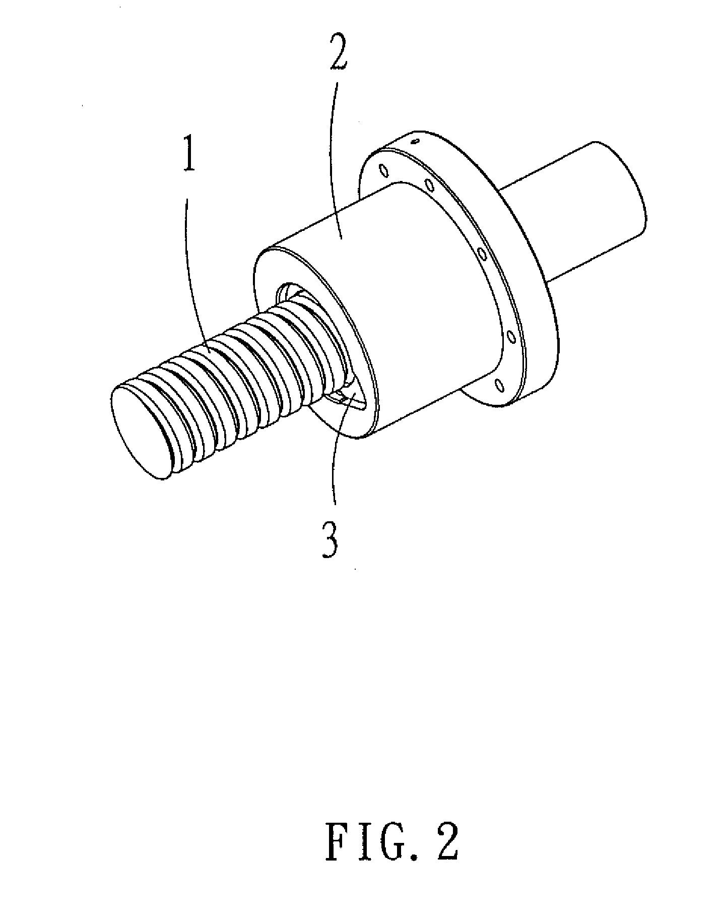
[0020]Referring to FIGS. 2-6, a roller screw system in accordance with a preferred embodiment of the present invention comprises a screw shaft 1, a nut 2, a pair of return members 3, a return pipe 4 and a plurality of rollers 5. The nut 2 is interiorly defined with a receiving recess 22 for accommodation of the return members 3, and an abutting surface 23.

[0021]The nut 2 is formed in its abutting surface 23 with a through hole 21 for connecting a return hole 30 in each of the return members 3.

[0022]Each of the return members 3 is interiorly defined with a return path for the rollers 5 and the return hole 30, and the return hole 30 is formed at the end thereof with a square cross section 31.

[0023]The return pipe 4 is formed with a return path f...


PUM


Abstract

A roller screw system comprises a screw shaft, a nut, a pair of return members, a return pipe and a plurality of rollers. The nut is interiorly defined with a receiving recess for accommodation of the return members, and an abutting surface. The roller screw system is characterized in that a through hole is defined in the nut and is in communication with the return hole. The return pipe is disposed in the through hole of the nut. The return members are disposed in the receiving groove of the nut, forming a return system. And the return system is to be connected to the helical groove of the screw shaft and the nut, thus forming a roller screw system. By such arrangements, the rollers can circulate more smoothly and the size of the nut will not be increased.

Description

BACKGROUND OF THE INVENTION[0001]1. Field of the Invention[0002]The present invention relates to a roller screw system, and more particularly to an engaging positioning structure between the return members and the return pipe, which is used in the roller screw to enable the rollers to circulate more smoothly and can reduce the size of the nut.[0003]2. Description of the Prior Art[0004]Linear guideway is used more and more widely in modern industries. In addition to its high precision transmission performance, the linear guideway also has many other advantages, such as low friction loss, high ratio of energy conversion, low noise, high rigidity and wear-resistance. Therefore, it is self-evident that the linear guideway is very important to various industrial mechanisms. Normally, the linear guideway is provided at both ends of its sliding block with a return portion (it is usually defined on the end caps of the sliding block) for enabling the rolling elements between the screw shaft ...

Claims


Application Information

Patent Timeline
Patent Type & Authority Applications(United States)
IPC IPC(8): F16H25/22
CPCY10T74/19767F16H25/2219
Inventor PAN, HUNG-SUNGWU, WEN-CHIA
Owner HIWIN TECH
Why Eureka
Try Eureka