Clinical drainage control device

A control device and drainage tube technology, applied in the direction of suction equipment, hypodermic injection equipment, suction pumping system, etc., can solve the problems of endangering the life of patients, large errors, and increasing the burden on medical staff and patients' families, so as to improve safety and Stability, guaranteed drainage effect, guaranteed effect of drainage effect

Inactive Publication Date: 2019-04-19
德州飚丰信息技术有限公司
View PDF0 Cites 0 Cited by
  • Summary
  • Abstract
  • Description
  • Claims
  • Application Information

AI Technical Summary

Problems solved by technology

[0004] In the clinical operation of drainage of a large amount of effusion, there are often specific requirements for clinical parameters such as daily drainage times, each drainage volume, and drainage speed according to the condition of the case. The parameters are usually controlled subjectively by the medical staff or the patient's family members. The current artificial control method has certain disadvantages. As a result, the drainage process cannot be carried out in the way the doctor expected, and the improper drainage will cause discomfort and injury to the patient, and even endanger the patient's life. On the other hand, the real-time drainage volume and drainage speed during the drainage process are usually determined by human observation. Judgment, the error is large, and it is difficult to guarantee the drainage effect. At the same time, the current control method will obviously increase the burden on the medical staff and the patient's family members.
[0005] The drainage bag is a relatively cheap medical product, and it is the best choice as the terminal container in clinical effusion drainage, but it can only be applied to conventional pleural effusion drainage operations under normal pressure, and cannot be applied to negative pressure drainage. Negative pressure drainage usually requires the use of water-sealed bottles that are more expensive than drainage bags, which brings a certain economic burden to patients

Method used


Image

  • Clinical drainage control device
  • Clinical drainage control device
  • Clinical drainage control device

Examples


Embodiment 1

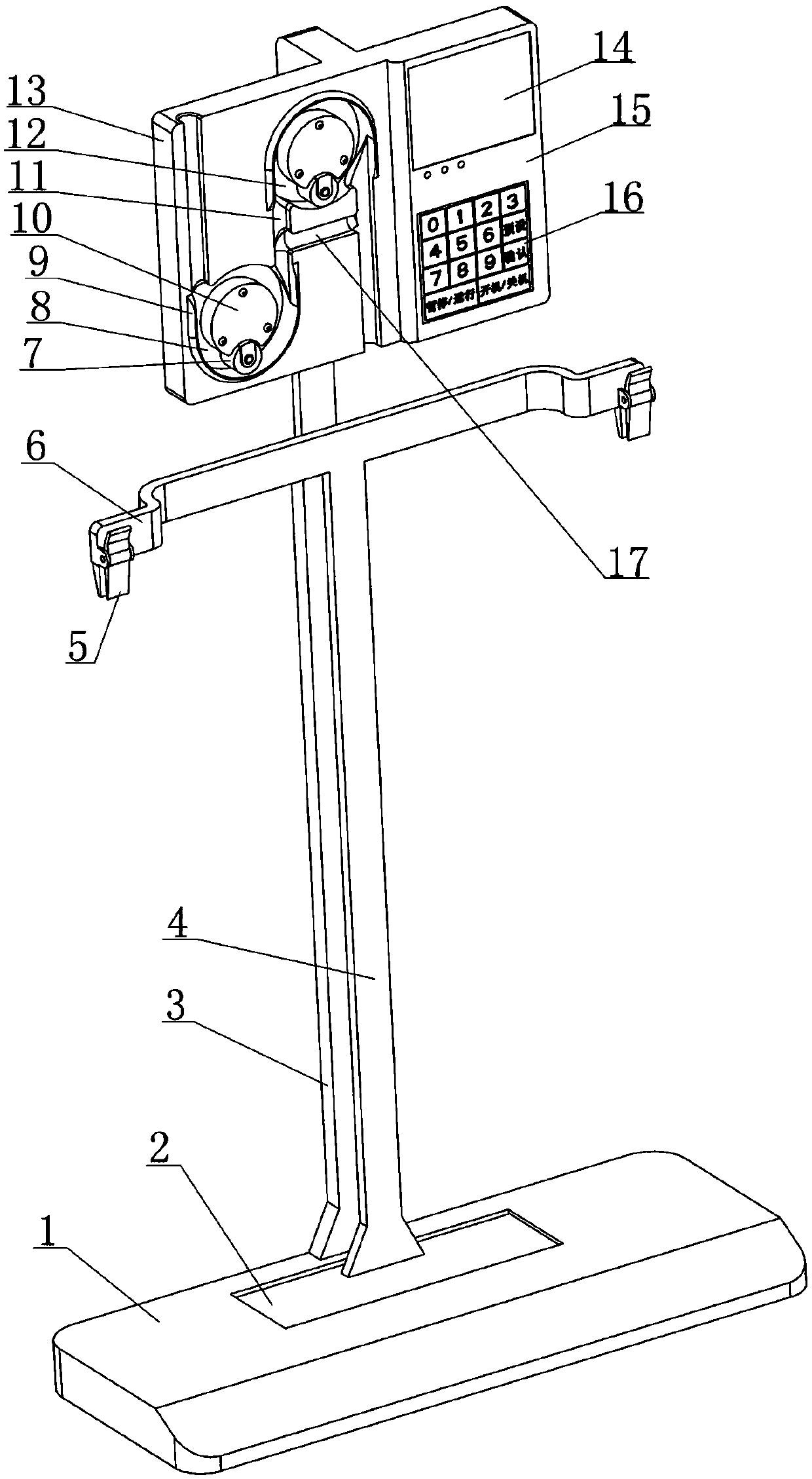
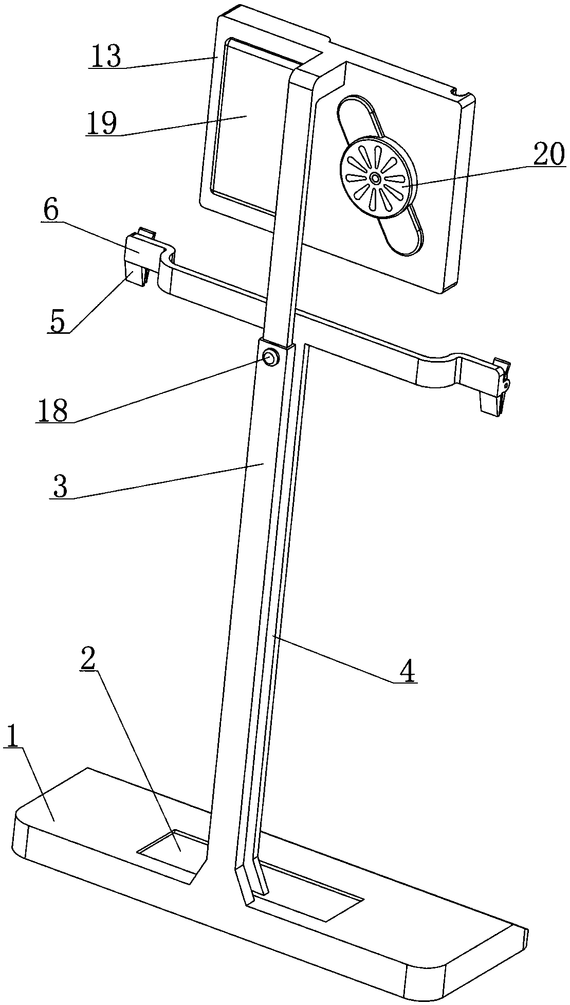
[0043] see figure 1 , 2 As shown, a clinical drainage control device disclosed in this embodiment is composed of a weighing base assembly, a suspension assembly, a drainage adjustment assembly, a controller 15 and a power supply assembly 19;

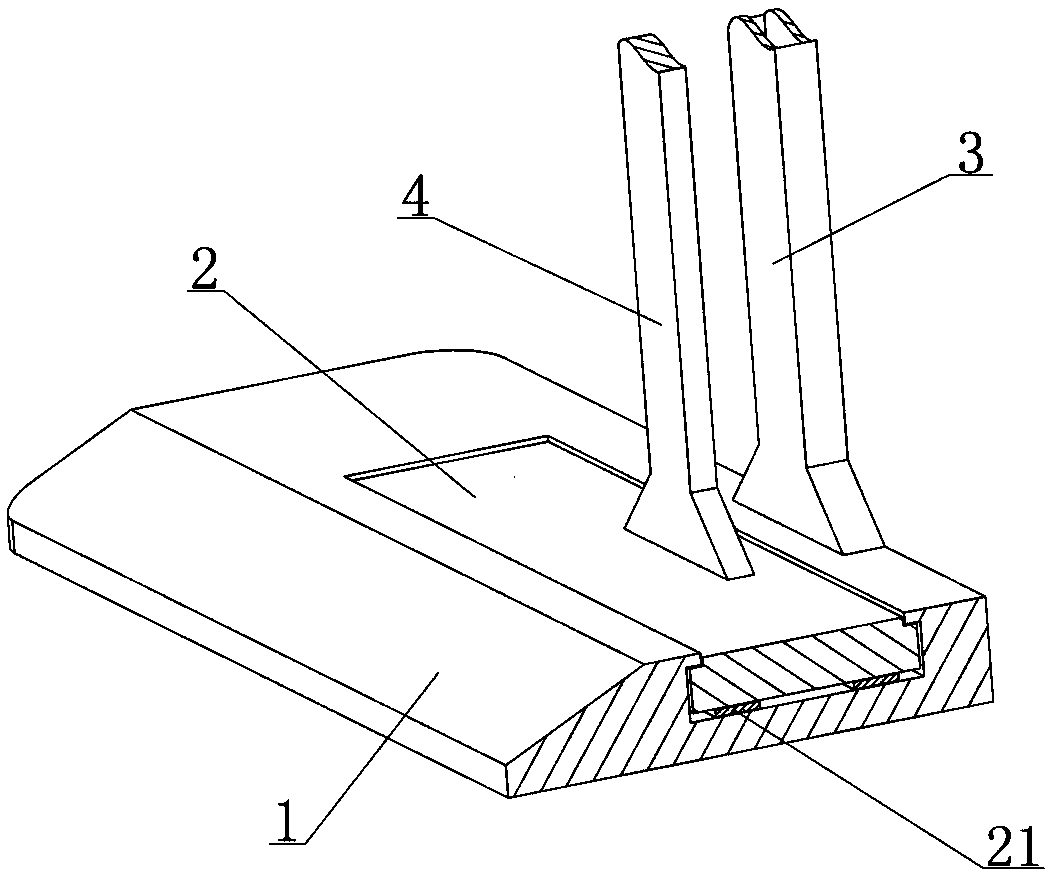
[0044] Among them, see figure 1 , 3 , 9, the weight-based base assembly is composed of a weighing platform 2, a load cell 21 and a base 1 that are sequentially matched up and down, and the load cell 21 outputs a weighing that can reflect the weight of the object above the weighing platform 2. Signal; on the one hand, the weight-based base component is used to provide basic support for the suspension component, the drainage adjustment component, the controller 15 and the power supply component 19, and on the other hand, it is used to feed back the weight signal to the controller 15;

[0045] Among them, see figure 1 , 9 , 10, the suspension assembly includes a vertical rod 4 and a suspension beam 6; the vertical rod 4 is in a vertica...

Embodiment 2

[0072] see Figure 6 , 7 As shown, in the clinical drainage control device disclosed in Embodiment 1, during the forward revolution of the roll 7, after entering the arc-shaped gap 8 each time, it can always move by rolling the drainage tube 22 through rotation, driving the drainage tube 22 to move. The fluid flows backwards to complete a fluid output; during this process, the pressure applied by the roller 7 to the drainage tube 22 should be appropriate. Effusion output efficiency, while the other side needs to prevent the roll 7 from causing excessive pressure on the drainage tube 22, avoiding the damage of the drainage tube 22 located in the arc gap 8, in order to ensure that the above two effects are balanced, the present embodiment is for the roll 7 has a further improvement in the way of cooperation with the orbital wheel 10, and the specific implementation structure is:

[0073] Such as Figure 12 As shown, the roll 7 is fixed in the roll fork 28 through the rotating...

Embodiment 3

[0076] see figure 1 , 3 , 9, in the clinical drainage control device disclosed in Embodiment 1, the controller 15 can obtain the weighing signal continuously fed back by the load cell 21 in real time. Data transmission requirements, this embodiment will obviously increase the overall manufacturing cost of the clinical drainage control device, and also reduce the working stability of the clinical drainage control device, it can be seen that the load cell 21 and the controller 15 are set for transmission The line of data is the best choice to ensure stability and economy, and in the same way, the operating current of the load cell 21 is provided by the power supply assembly 19 through wires and is also the best choice to ensure stability and economy; but there is The problem is that the controller 15 and the power supply assembly 19 are located on the installation board 13, and the two are distributed up and down with the load cell 21. In addition, the controller 15 and the pow...


PUM


Abstract

The invention relates to the field of medical instruments, and discloses a clinical drainage control device. The device comprises a weighing base assembly, a suspension assembly, a drainage adjustmentassembly, a controller and a power source assembly; during the drainage process, the suspension assembly can provide support for a drainage bag, the weighing base assembly can feed back a weight signal reflecting the change of accumulated liquid in the drainage bag to the controller, the drainage adjustment assembly includes a first rolling mechanism and a second rolling mechanism of which working states are regulated by the controller, by means of the first rolling mechanism and the second rolling mechanism, the negative pressure drainage process can be achieved and regulated, and the firstrolling mechanism can be used for regulating the normal pressure drainage process. The clinical drainage control device adopts an intelligent design, can cooperate with an existing conventional drainage assembly to achieve automatic control of timing drainage, quantitative drainage and constant velocity drainage, improves the safety and stability of the drainage operation, has two drainage modes of the normal pressure drainage and the negative pressure drainage, and can meet most of clinical drainage needs.

Description

[0001] The present invention is a divisional application of the invention patent application with application number 2018111350948 submitted on September 28, 2018. technical field [0002] The invention relates to the technical field of medical devices, in particular to an intelligent control device for clinical drainage assistance. Background technique [0003] Under normal conditions, there is a small amount of fluid in the thoracic cavity and abdominal cavity of the human body, which can lubricate the organs in the cavity. If the amount of fluid in the cavity increases beyond the normal physiological range under pathological conditions, it will become a disease, such as pleural effusion and ascites. There are many causes of peritoneal effusion and pleural effusion, which are very common clinical diseases. Although peritoneal effusion and pleural effusion are only one symptom, a large amount of peritoneal effusion and large amount of peritoneal effusion will cause a series...

Claims


Application Information

Patent Timeline
Patent Type & Authority Applications(China)
IPC IPC(8): A61M1/00
CPCA61M1/0023A61M2205/3334A61M1/74
Inventor 王才丰
Owner 德州飚丰信息技术有限公司
Why Eureka
Try Eureka