This helps you quickly interpret patents by identifying the three key elements:
Problems solved by technology
Method used
Benefits of technology
Problems solved by technology
[0004] In the clinical operation of drainage of a large amount of effusion, there are often specific requirements for clinical parameters such as daily drainage times, each drainage volume, and drainage speed according to the condition of the case. The parameters are usually controlled subjectively by the medical staff or the patient's family members. The current artificial control method has certain disadvantages. As a result, the drainage process cannot be carried out in the way the doctor expected, and the improper drainage will cause discomfort and injury to the patient, and even endanger the patient's life. On the other hand, the real-time drainage volume and drainage speed during the drainage process are usually determined by human observation. Judgment, the error is large, and it is difficult to guarantee the drainage effect. At the same time, the current control method will obviously increase the burden on the medical staff and the patient's family members.
[0005] The drainage bag is a relatively cheap medical product, and it is the best choice as the terminal container in clinical effusion drainage, but it can only be applied to conventional pleural effusion drainage operations under normal pressure, and cannot be applied to negative pressure drainage. Negative pressure drainage usually requires the use of water-sealed bottles that are more expensive than drainage bags, which brings a certain economic burden to patients
Method used
Image
Click on the blue label to locate the original text in one second.
Reading with bidirectional positioning of images and text.
Examples
Embodiment 1
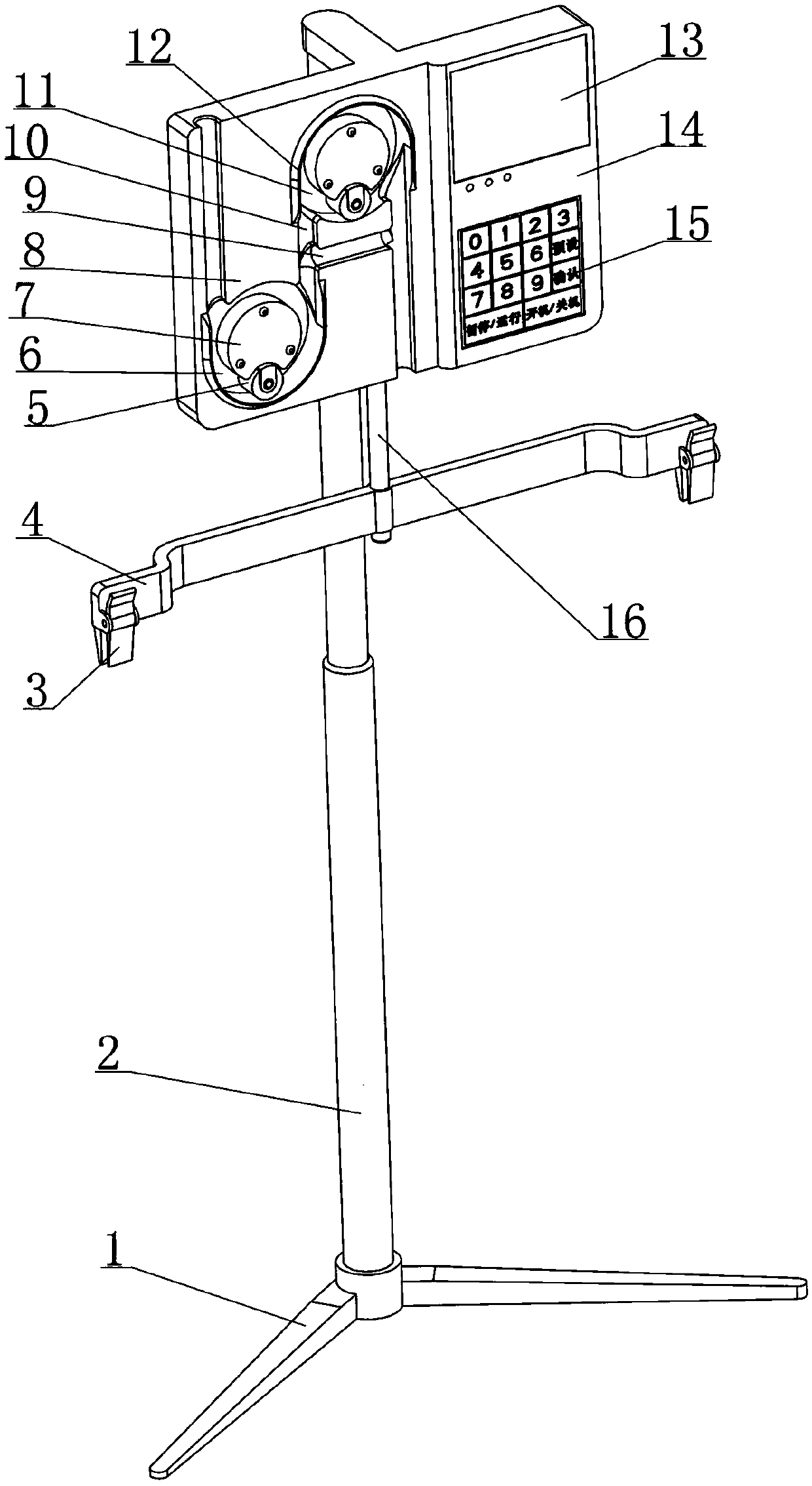
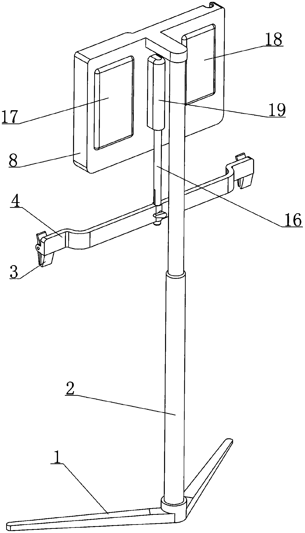
[0045] see figure 1 , 2 As shown, a multifunctional medical drainage device disclosed in this embodiment includes five parts: a support assembly, a weighted suspension assembly, a drainage adjustment assembly, a controller 14 and a power supply assembly 17;
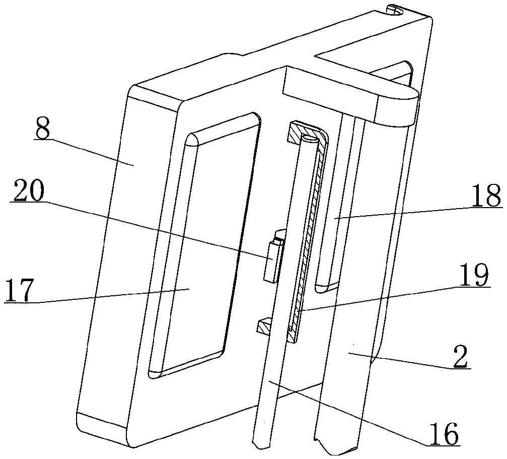
[0046] Among them, see figure 1 , 2 As shown, the support assembly includes a base 1, a column 2 and a mounting plate 8; the column 2 is supported by the base 1 and extends in the vertical direction, the mounting plate 8 is supported by the column 2, and the mounting plate 8 is located above the base 1 , the front side of the column 2; the placement plate 8 is used to provide a placement space for the gravimetric suspension assembly, the drainage adjustment assembly, the controller 14 and the power supply assembly 17, and provide support directly or indirectly;
[0047] Among them, see figure 2 , 3 , 9, and 10, the described gravimetric suspension assembly includes a weighing bar 16 and a suspension beam 4; the midd...
Embodiment 2
[0077] see Figure 6 , 7 As shown, in the multifunctional medical drainage device disclosed in Embodiment 1, during the forward revolution of the roller 5, after entering the arc-shaped gap 6 each time, it can always move by rolling the drainage tube 21 by rotation, driving the drainage tube 21 The fluid flows backwards to complete a fluid output; during this process, the pressure exerted by the roll 5 on the drainage tube 21 should be appropriate, on the one hand, the drainage tube 21 should be squeezed toward the curved side wall 12 as much as possible, thus Improve the output efficiency of the effusion, while the other side needs to prevent the roller 5 from causing excessive pressure on the drainage tube 21, and avoid damage to the drainage tube 21 located in the arc-shaped gap 6. In order to ensure that the effects of the above two aspects are balanced, this embodiment is for The cooperation mode of roll 5 and orbital wheel 7 has further improvement, and concrete impleme...
Embodiment 3
[0081] see Figure 9 As shown, in the clinical use of the multifunctional medical drainage device disclosed in Example 1, its specific installation position is directly determined by the position of the patient and the layout of the 21 channels of the drainage tube. It is beneficial for the operator to perform operations such as parameter presets through the operation keys, or it is not conducive for the operator to know the drainage status by observing the display screen 13, which brings certain inconvenience to the clinical operation; in order to solve this defect, this embodiment implements On the basis of the structure of the multifunctional medical drainage device disclosed in Example 1, there is further improvement, and the specific structure is as follows:
[0082] Such as Figure 14 As shown, the multifunctional medical drainage device is equipped with a remote control device, the remote control device is provided with a wireless transmission module, a display element...
PUM
Abstract
The invention relates to the field of medical instruments and discloses a multifunctional medical drainage device. The multifunctional medical drainage device comprises a supporting seat assembly, a weighing sling assembly, a drainage adjusting assembly, a controller and a power supply component, wherein the weighing sling assembly can support a drainage bag and feeds back the change state of weight of hydrops in the drainage bag to the controller; the drainage adjusting assembly comprises a first tube rolling mechanism and a second tube rolling mechanism of which work states are regulated bythe controller; the first tube rolling mechanism and the second tube rolling mechanism commonly act on a drainage tube to realize and regulate the negative pressure drainage process; normal pressure drainage is regulated by means of the first tube rolling mechanism. The multifunctional medical drainage device adopts intellectualized design; by matched use of the multifunctional medical drainage device and an existing conventional drainage assembly, automatic control over timing drainage, quantitative drainage and constant-speed drainage can be realized, and safety and stability of drainage operation are improved; the multifunctional medical drainage device has two drainage modes of normal pressure drainage and negative pressure drainage and can meet most clinical drainage demands.
Description
[0001] The present invention is a divisional application of the invention patent application with application number 201811135069X submitted on September 28, 2018. technical field [0002] The invention relates to the technical field of medical devices, in particular to an intelligent control device for clinical drainage assistance. Background technique [0003] Under normal conditions, there is a small amount of fluid in the thoracic cavity and abdominal cavity of the human body, which can lubricate the organs in the cavity. If the amount of fluid in the cavity increases beyond the normal physiological range under pathological conditions, it will become a disease, such as pleural effusion and ascites. There are many causes of peritoneal effusion and pleural effusion, which are very common clinical diseases. Although peritoneal effusion and pleural effusion are only one symptom, a large amount of peritoneal effusion and large amount of peritoneal effusion will cause a series...
Claims
Application Information
Patent Timeline
Application Date:The date an application was filed.
Publication Date:The date a patent or application was officially published.
First Publication Date:The earliest publication date of a patent with the same application number.
Issue Date:Publication date of the patent grant document.
PCT Entry Date:The Entry date of PCT National Phase.
Estimated Expiry Date:The statutory expiry date of a patent right according to the Patent Law, and it is the longest term of protection that the patent right can achieve without the termination of the patent right due to other reasons(Term extension factor has been taken into account ).
Invalid Date:Actual expiry date is based on effective date or publication date of legal transaction data of invalid patent.

