
Axial and lateral bidirectional simple centering equipment of gas turbine

A centering device and gas turbine technology, applied in metal processing, metal processing equipment, manufacturing tools, etc., can solve the problems of time-consuming, labor-intensive, low adjustment accuracy, etc., achieve simple installation and operation methods, strong versatility, and improve work efficiency Effect

Pending Publication Date: 2019-04-19
中国船舶重工集团公司第七0三研究所
View PDF8 Cites 2 Cited by
  • Summary
  • Abstract
  • Description
  • Claims
  • Application Information

AI Technical Summary

Problems solved by technology

[0004] In order to solve the problems of low adjustment accuracy and time-consuming and labor-intensive centering process in the existing centering equipment, the present invention further provides a gas turbine axial and lateral two-way simple centering device

Method used


Image

  • Axial and lateral bidirectional simple centering equipment of gas turbine
  • Axial and lateral bidirectional simple centering equipment of gas turbine
  • Axial and lateral bidirectional simple centering equipment of gas turbine

Examples


specific Embodiment approach 1

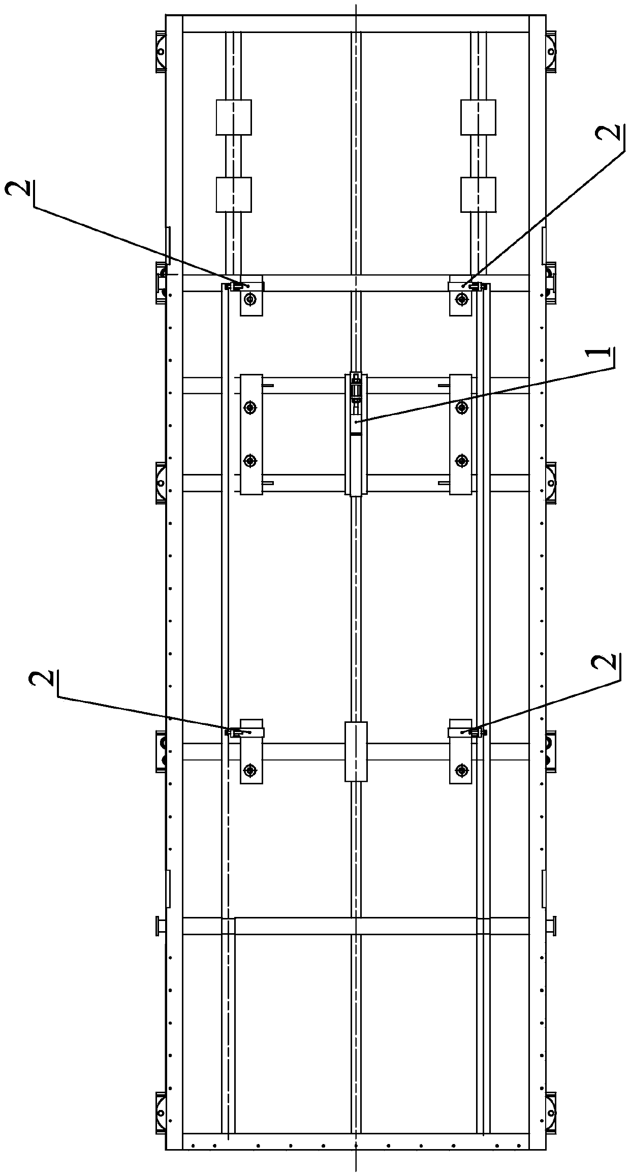
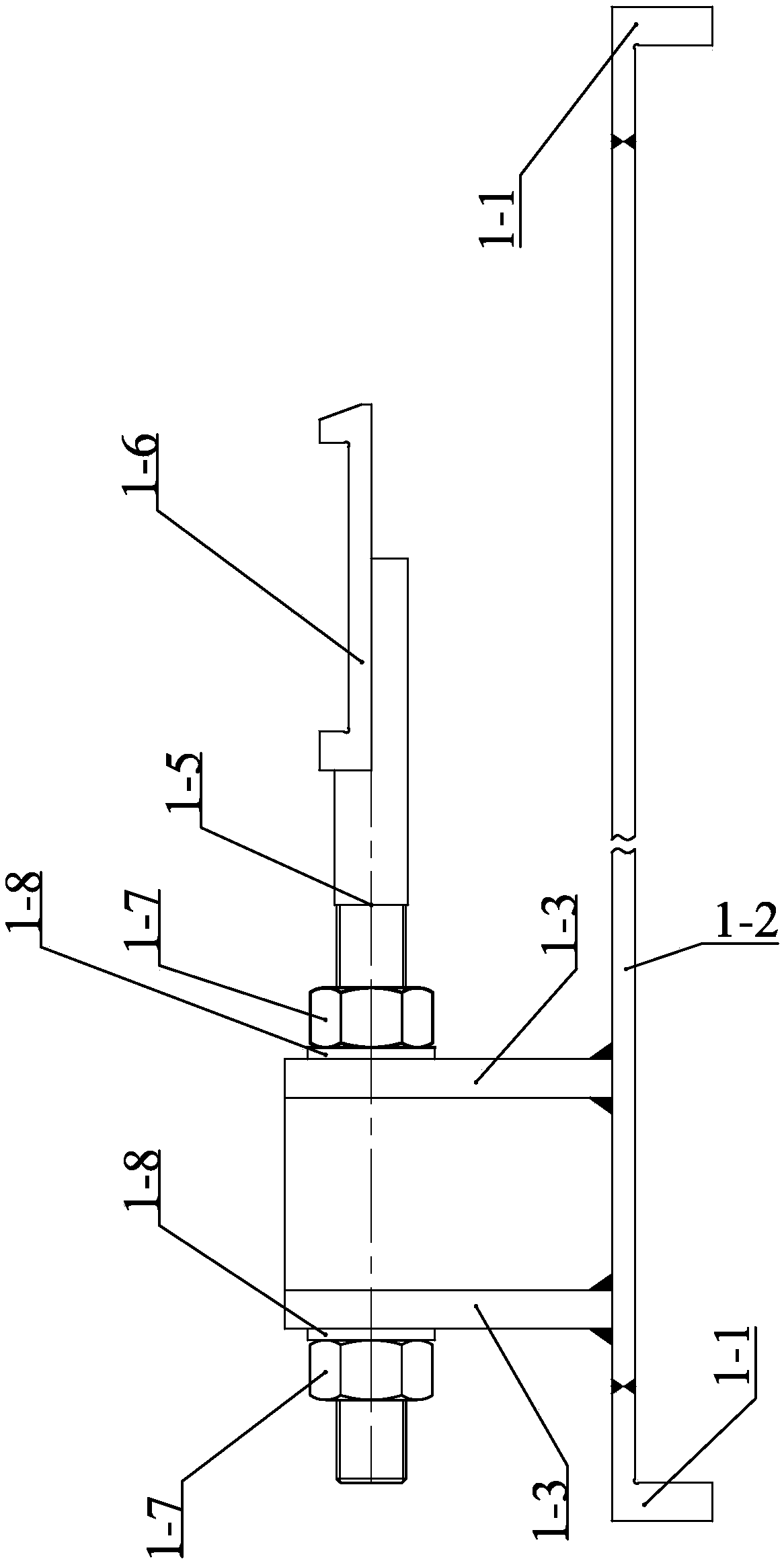
[0016] Embodiment 1: According to Figures 1 to 5 Illustrating this embodiment, a simple axial and lateral bidirectional centering device for a gas turbine includes an axial centering device 1 and a lateral centering device 2; the axial centering device 1 includes an end plate 1-1, a No. 1 base plate 1-2, support plate 1-3, tie rod 1-5, connecting plate 1-6 and nut 1-7; end plate 1-1 is fixedly connected to both ends of No. 1 base plate 1-2; support plate 1-3 The number is two, and they are all "U"-shaped plates. The support plates 1-3 are vertically fixed and connected to the No. 1 base plate 1-2 with the open end upward. The two support plates 1-3 are parallel to each other along the No. 1 base plate 1- 2. Set in the length direction; one end of the tie rod 1-5 is provided with a thread, the threaded end of the tie rod 1-5 passes through the "U"-shaped grooves of the two support plates 1-3, and is fixed with a nut on the outside of the support plate 1-3, and the pull rod Th...

specific Embodiment approach 2

[0017] Specific implementation two: according to figure 1 Illustrating this embodiment, the simple axial and lateral two-way centering device for a gas turbine further includes a large chassis 3, and the axial centering device 1 and the lateral centering device 2 are arranged on the large chassis 3, and the four Two lateral centering devices 2 are respectively arranged at the four corners of the large chassis 3, and one axial centering device 1 is disposed in the middle of the large chassis. Other components and connection relationships are the same as in the first embodiment.

specific Embodiment approach 3

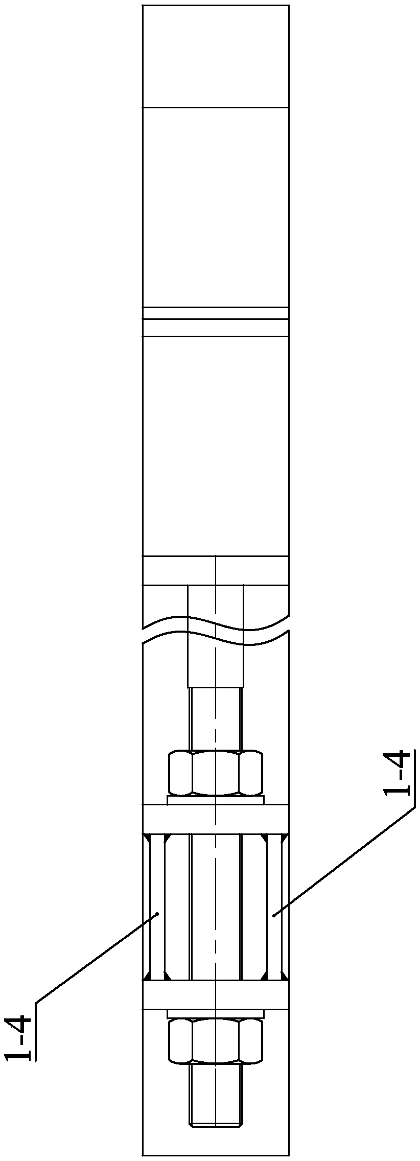
[0018] Specific implementation three: according to image 3 Illustrating this embodiment, the axial centering device 1 further includes an intermediate plate 1-4, the intermediate plate 1-4 is a rectangular plate, and is vertically and fixedly connected between the two support plates 1-3. The addition of the intermediate plate makes the axial centering device 1 more stable during operation. Other compositions and connection relationships are the same as in the second embodiment.


PUM


Abstract

The invention discloses axial and lateral bidirectional simple centering equipment of a gas turbine and relates to the field of gas turbine centering, and the problems that the existing centering equipment is low in adjustment precision and time and labor are wasted in the centering process are solved. The axial and lateral bidirectional simple centering equipment of the gas turbine comprises an axial centering device and four lateral centering devices, wherein the four lateral centering devices are located on the periphery of the axial centering device; the axial centering device comprises end plates, a first bottom plate, supporting plates, a pull rod, a connecting plate and nuts; and each lateral centering device comprises a second bottom plate, a vertical plate, rib plates and a bolt.The axial and lateral bidirectional simple centering equipment is applied to a gas turbine installation process and is in precise centering with other load equipment.

Description

technical field [0001] The invention relates to the field of gas turbine centering, in particular to an axial and lateral bidirectional simple centering device for a gas turbine. Background technique [0002] After the overhaul of the domestic 30MW gas-driven compressor unit and other types of gas turbines, the gas turbine needs to be re-installed, and the re-installation process requires precise alignment of the gas turbine and the compressor or other load equipment. Since the gas turbine is re-installed and the anchor bolts of other load equipment such as the compressor are not loose, the position of the gas turbine is generally adjusted for centering; due to the large size and mass of the gas turbine, the horizontal position movement is inconvenient and the movement accuracy is low. The alignment devices used for gas turbines and load equipment are tools such as guide chains and jacks. Since the guide chains and jacks have no installation position, they are inconvenient t...

Claims


Application Information

Patent Timeline
Patent Type & Authority Applications(China)
IPC IPC(8): B23P19/10
CPCB23P19/10
Inventor 孙鹏张建国栾永军康文武刘博关琦冉军辉孔庆毅白冰骆平平郑涛
Owner 中国船舶重工集团公司第七0三研究所
Learn More