Vehicle body structure

A technology of structure and body, applied in the direction of vehicle components, substructure, superstructure, etc., can solve problems such as difficult collision load transfer

Active Publication Date: 2019-04-19
VERITEC INCORPORATED +1
View PDF9 Cites 0 Cited by
  • Summary
  • Abstract
  • Description
  • Claims
  • Application Information

AI Technical Summary

Problems solved by technology

As a result, it becomes more difficult to transmit the collision load input to the load receiving portion to the frame, and it becomes difficult to move the front portion of the vehicle to the side away from the obstacle in the vehicle width direction.

Method used


Image

  • Vehicle body structure
  • Vehicle body structure
  • Vehicle body structure

Examples


Embodiment Construction

[0032] Embodiments of the present invention will be described below based on the drawings.

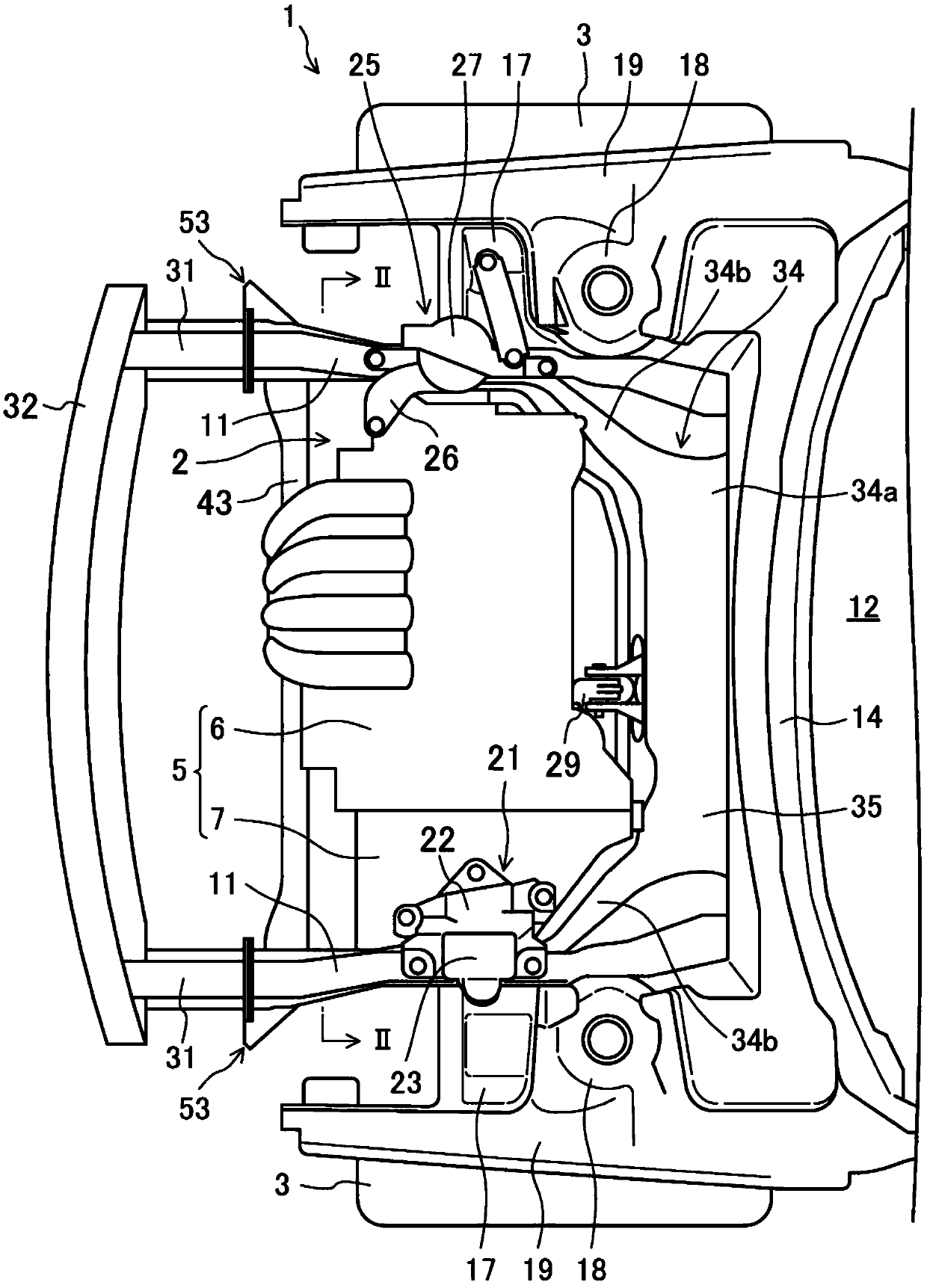
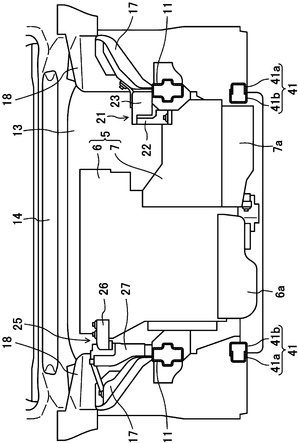
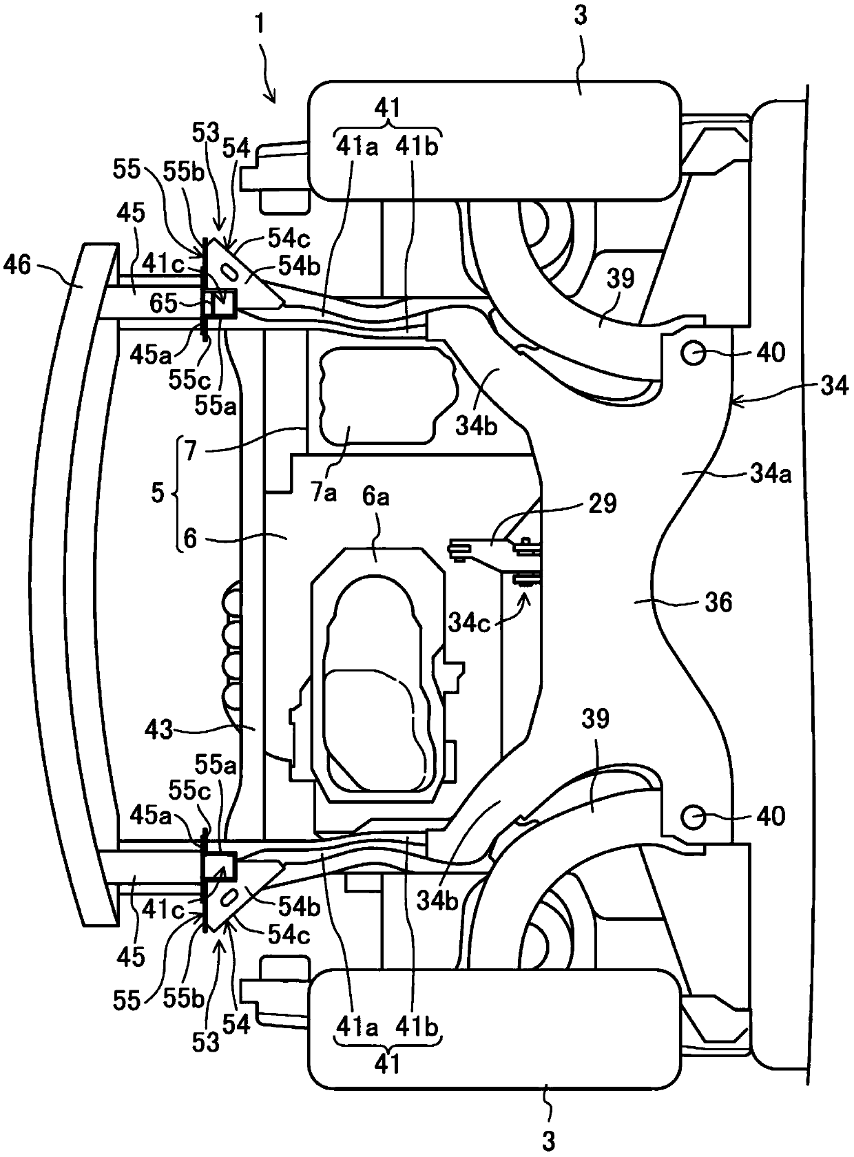
[0033] Figure 1 ~ Figure 3 The main part of the front part of the vehicle 1 to which the vehicle body structure of embodiment of this invention is applied is shown. A powertrain 5 that drives left and right front wheels 3 of the vehicle 1 is arranged in an engine compartment 2 at the front of the vehicle 1 . The powertrain 5 is composed of an engine 6 and a transmission 7 into which torque (power) generated by the engine 6 is input. Hereinafter, the front, rear, left, right, up and down of the vehicle 1 are referred to as front, rear, left, right, up and down, respectively.

[0034] The engine 6 and the transmission 7 are arranged along the vehicle width direction (left-right direction) between a pair of left and right front side frames 11 described later, and in the present embodiment, the engine 6 is located on the right side of the transmission 7 . The lower end portion of the e...


PUM


Abstract

The present invention provides a vehicle body structure to achieve light weight of a frame body (an extending frame (41)) and effectively transmitting the corrosion load input to a load bearing portion (53) to the frame body when the vehicles are crashed in an overlapping mode in a small range. A cutout portion (41c) is arranged at the end face of the front side of the vehicle of the frame and isformed by cut-off rearwardly from the front end, and the side portions of two sides in the vehicle width direction of the cutout portion (41c) are connected to each other through a connection part (65).

Description

technical field [0001] The present invention relates to a vehicle body structure provided with a frame body along the vehicle front-rear direction on the outside of a powertrain mounted on a front portion of a vehicle in the vehicle width direction. Background technique [0002] Conventionally, in the event of a frontal collision of a vehicle, it is known that a collision load is absorbed by deformation of a frame body (a front side frame and an extension frame extending from a suspension cross member toward the vehicle front side). Also, as one form of frontal collision of a vehicle, the vehicle may collide with an obstacle on the outer side in the vehicle width direction than the front side frame of the vehicle, and such a frontal collision is called a small-area overlap collision. In order to cope with such a small-scale overlapping collision, it is known to provide a load receiving portion protruding outward in the vehicle width direction at the front end of the front si...

Claims


Application Information

Patent Timeline
Patent Type & Authority Applications(China)
IPC IPC(8): B62D25/08B62D21/15
CPCB62D21/152B62D25/082B62D25/08B60R19/34
Inventor 内场友贵川本笃史木户启人石川靖金丸大辅佐野晋向井北斗神保泰成
Owner VERITEC INCORPORATED
Why Eureka
Try Eureka