RFID antenna and equipment terminal therewith

A technology of equipment terminals and antennas, applied in the field of RFID, can solve problems such as poor recognition effect, achieve the effects of improving recognition effect, increasing reading distance, and optimizing performance

Pending Publication Date: 2019-04-19
SHENZHEN KELU INTERNET OF THINGS INFORMATION TECH CO LTD
View PDF0 Cites 0 Cited by
  • Summary
  • Abstract
  • Description
  • Claims
  • Application Information

AI Technical Summary

Problems solved by technology

At present, most application scenarios still use handheld terminals to read data, but the antenna standing wave ratio of handheld terminals is generally around 1.5, and the recognition effect is not very good

Method used


Image

  • RFID antenna and equipment terminal therewith
  • RFID antenna and equipment terminal therewith
  • RFID antenna and equipment terminal therewith

Examples


Embodiment Construction

[0026] It should be noted that, in the case of no conflict, the embodiments in the present application and the features in the embodiments can be combined with each other.

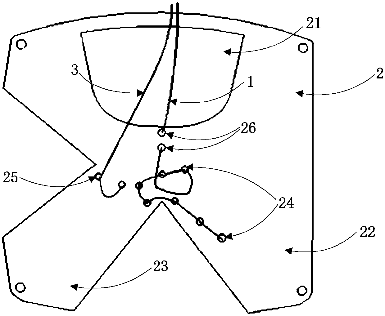
[0027] The invention discloses an RFID antenna, such as figure 1 As shown, the RFID antenna includes a wire antenna 1 and a metal plate 2 . Wherein, the linear antenna 1 is wound into an S-shaped structure and fixed above the metal plate 2, the first end of the linear antenna 1 is electrically connected to the metal plate 2, and the second end of the linear antenna 1 is used to connect the circuit board .

[0028] In order to assist in adjusting the standing wave ratio, the RFID antenna also includes a feeder 3 . One end of the feeder 3 is electrically connected to the metal plate 2, and the other end of the feeder 3 is used to connect the circuit board.

[0029] In this embodiment, the metal plate 2 has an R-shaped structure, and the R-shaped structure includes an upper half and a lower half. Wherein,...


PUM


Abstract

The invention discloses an RFID antenna and an equipment terminal therewith. The RFID antenna comprises a linear antenna, a metal plate and a feeder line, wherein the linear antenna is wound into an S-shaped structure and is fixed above the metal plate. The first end of the linear antenna is electrically connected with the metal plate, and the second end of the linear antenna is connected with a circuit board. One end of the feeder line is electrically connected with the metal plate, and the other end of the feeder line is connected with the circuit board. The equipment terminal comprises theRFID antenna, an upper cover, a lower cover and a circuit board. According to the invention, through a specific wiring mode, the antenna standing-wave ratio is reduced, and the performance of the RFIDantenna is optimized. The technical problems that in the prior art, the reading distance is short, and the standing wave ratio is high are solved, and therefore the RFID antenna and the equipment terminal which are beneficial for increasing the reading distance and improving the recognition effect are provided.

Description

technical field [0001] The invention relates to the field of RFID, in particular to an RFID RFID antenna and a device terminal with the antenna. Background technique [0002] RFID: Radio Frequency Identification, radio frequency identification, is a communication technology that can identify specific targets and read related data through radio signals. [0003] Standing wave ratio: The ratio of the standing wave antinode voltage to the valley voltage amplitude, which is used to indicate whether the antenna and the radio wave transmitter are matched. [0004] As the field of application of RFID identification technology becomes wider and wider, more users feel the convenience and efficiency brought by RFID technology. RFID industrial tablet computers are used in many fields. In the existing technology of RFID tablet computers, an RFID identification system mainly composed of three parts: RFID antenna, reader, and electronic tag is usually used. The RFID antenna communicates...

Claims


Application Information

Patent Timeline
IPC IPC(8): H01Q1/22H01Q1/36H01Q1/50
CPCH01Q1/2208H01Q1/2258H01Q1/36H01Q1/50
Inventor 唐凯
Owner SHENZHEN KELU INTERNET OF THINGS INFORMATION TECH CO LTD
Why Eureka
Try Eureka