RFID (Radio Frequency Identification) high-gain circularly polarized microstrip antenna array

A technology of microstrip antenna and circular polarization, which is applied to the combination of antenna units with different polarization directions, antenna, antenna coupling, etc., can solve the problems of narrow half-power beam width, low antenna gain, narrow frequency band, etc., and achieve high reading The effect of taking distance, increasing the front-to-back ratio, and reducing the VSWR

Active Publication Date: 2013-12-25
CHENGDU JIUZHOU ELECTRONIC INFORMATION SYSTEM CO LTD
View PDF5 Cites 9 Cited by
  • Summary
  • Abstract
  • Description
  • Claims
  • Application Information

AI Technical Summary

Problems solved by technology

[0004] The invention provides an RFID high-gain circularly polarized microstrip antenna array, aiming to solve the problems of low gain, high axial ratio, narrow half-power beam width, and narrow frequency band of existing RFID antennas working in the UHF frequency band.

Method used


Image

  • RFID (Radio Frequency Identification) high-gain circularly polarized microstrip antenna array
  • RFID (Radio Frequency Identification) high-gain circularly polarized microstrip antenna array
  • RFID (Radio Frequency Identification) high-gain circularly polarized microstrip antenna array

Examples


Embodiment Construction

[0021] In order to make the object, technical solution and advantages of the present invention clearer, the present invention will be further described in detail below in conjunction with the accompanying drawings and embodiments. It should be understood that the specific embodiments described here are only used to explain the present invention, not to limit the present invention.

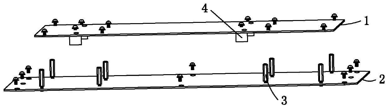
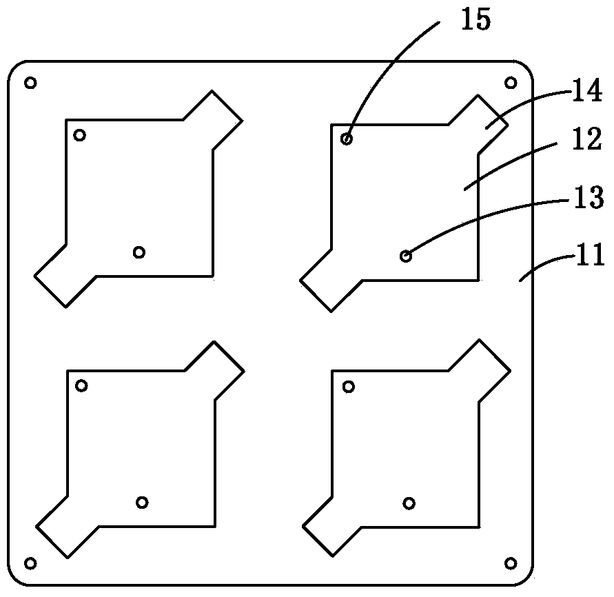
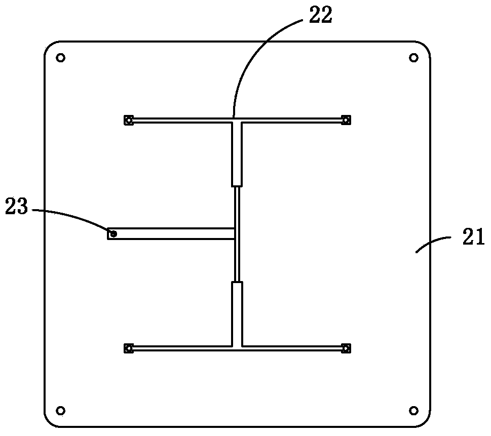
[0022] Such as figure 1 , 2 As shown in . A radiating unit 12, the reflector 2 includes a reflector dielectric substrate 21 and a feed network 22 positioned on the surface of the reflector dielectric substrate 21, each radiating unit 12 is provided with a radiating unit feed point 13, each radiating The two opposite corners of the unit 12 are provided with supplementary angles 14 and the positions of the supplementary angles 14 on the four radiating units 12 are consistent; The network 22 is connected.

[0023] In this embodiment, a microstrip antenna array composed of four radiating units 12 i...


PUM


Abstract

The invention discloses an RFID (Radio Frequency Identification) high-gain circularly polarized microstrip antenna array. The RFID high-gain circularly polarized microstrip antenna array comprises a radiation plate and a reflection plate, wherein the radiation plate comprises a radiation plate dielectric substrate and four radiation units on the surface of the radiation plate dielectric substrate, a radiation unit feed point is arranged on each radiation unit, the reflection plate comprises a reflection plate medium substrate and a feed network on the surface of the reflection plate medium substrate, and the radiation unit feed points are connected with the feed network through support columns and signal wires on the support columns; supplementary angles are formed on two opposite angles of each radiation unit, the positions of the supplementary angles on the four radiation units are consistent, and circularly polarized radiation of antennas is realized by combining a one-point central feed way with the supplementary angles. In order to reduce a standing wave ratio and improve radiation efficiency, the RFID high-gain circularly polarized microstrip antenna array further comprises four tuning aluminum columns which are fixed on the radiation plate. The RFID high-gain circularly polarized microstrip antenna array disclosed by the invention has the advantages of high gain, low axial ratio, half-power wave bandwidth, wide radiation frequency and the like.

Description

technical field [0001] The invention belongs to the technical field of wireless communication, and in particular relates to an RFID high-gain circularly polarized microstrip antenna array. Background technique [0002] Radio Frequency Identification (RFID, Radio Frequency Identification) is an emerging automatic identification technology, that is, two-way data communication through wireless means, and then identify the target. A typical RFID system consists of electronic tags, readers and related software. Since the identification can be completed without physical contact between the RFID tag and the reader, the RFID system can work in harsh environments and realize the identification of multiple moving targets. [0003] In the RFID system, the reader sends a radio frequency signal of a specific frequency through the antenna. When the tag enters the area, the tag obtains the reader command from the radiation field, processes it through the tag circuit, and then sends out it...

Claims


Application Information

Patent Timeline
Patent Type & Authority Applications(China)
IPC IPC(8): H01Q1/38H01Q1/50H01Q1/52H01Q19/10H01Q21/24
Inventor 黄俊祥王新国邓有明刘玲玲高凯
Owner CHENGDU JIUZHOU ELECTRONIC INFORMATION SYSTEM CO LTD
Why Eureka
Try Eureka