

Antenna device for HF and LF operation
a technology of inductive antenna and lf antenna, which is applied in the direction of antennas, antenna adaptation in movable bodies, antenna supports/mountings, etc., can solve the problems of not allowing different performance of hf antennas, and cannot work at a frequency range comprised between 3 and 30 mhz when working as hf antennas, so as to improve the reading distance of hf antennas and increase the reliability of multi-purpose antenna devices.
- Summary
- Abstract
- Description
- Claims
- Application Information
AI Technical Summary
Benefits of technology
Problems solved by technology
Method used
Image

Examples
Embodiment Construction
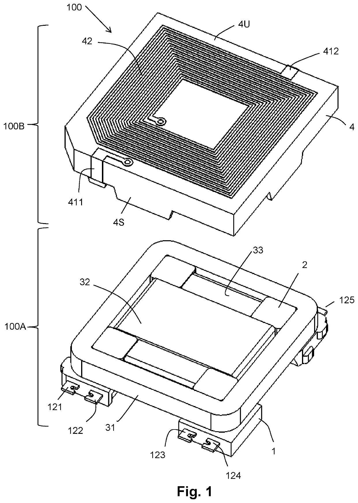
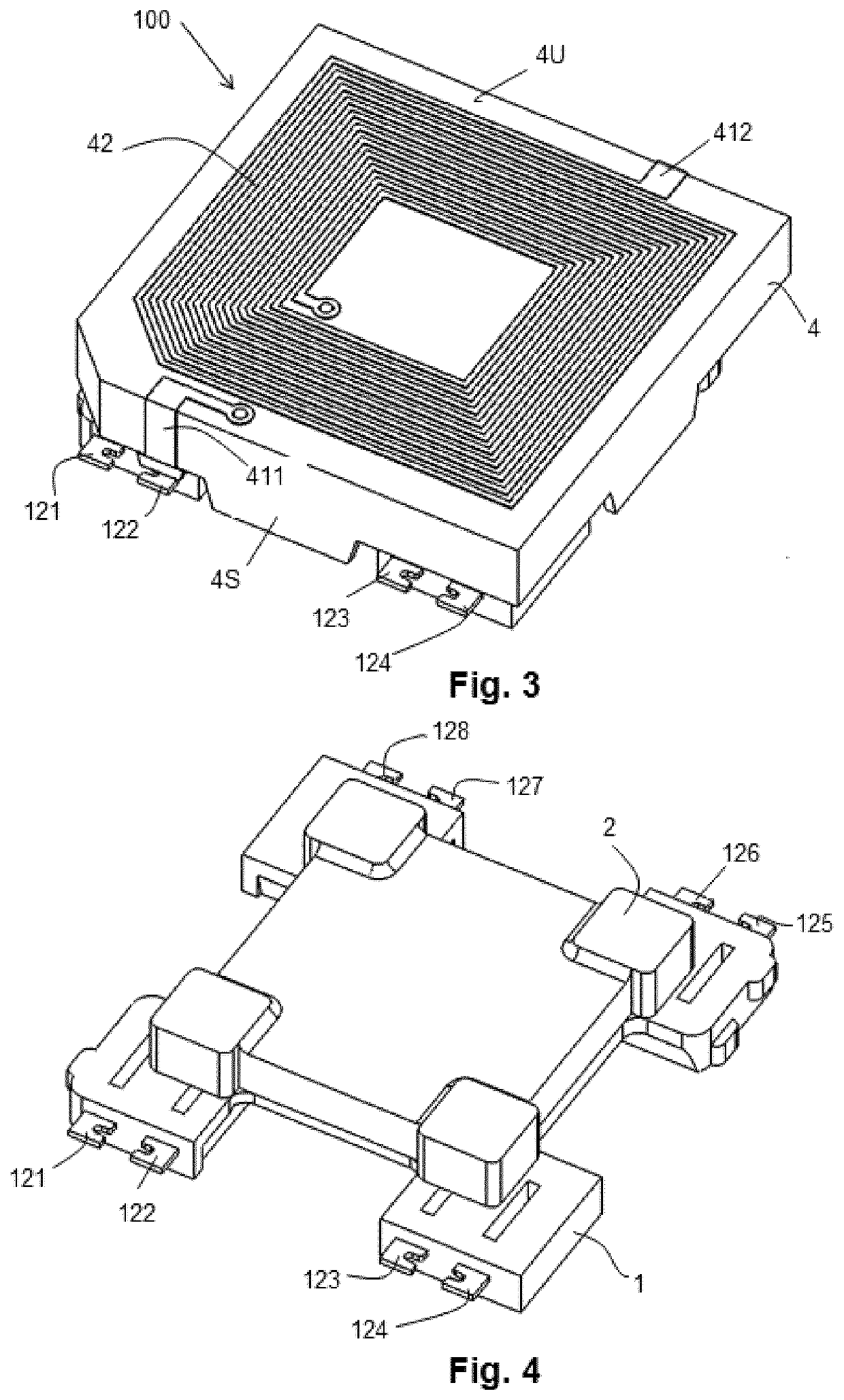
[0008]Embodiments of the present invention provide an antenna device, comprising as commonly in the field, at least one magnetic core; one or more windings wound around said magnetic core providing a LF antenna adapted to work at a frequency comprised in a range between 20 and 150 kHz, and an electrically insulated base, on which the magnetic core wound with the winding or windings is arranged. The electrically insulated base includes metallic tabs at least part of which are electrically connected to said winding or windings and the electrically insulated base has a bottom surface with electrically conductive plates providing a layout intended for a SMT mounting, wherein at least one of said metallic tabs of the electrically insulated base is connected to at least one of the electrically conductive plates.
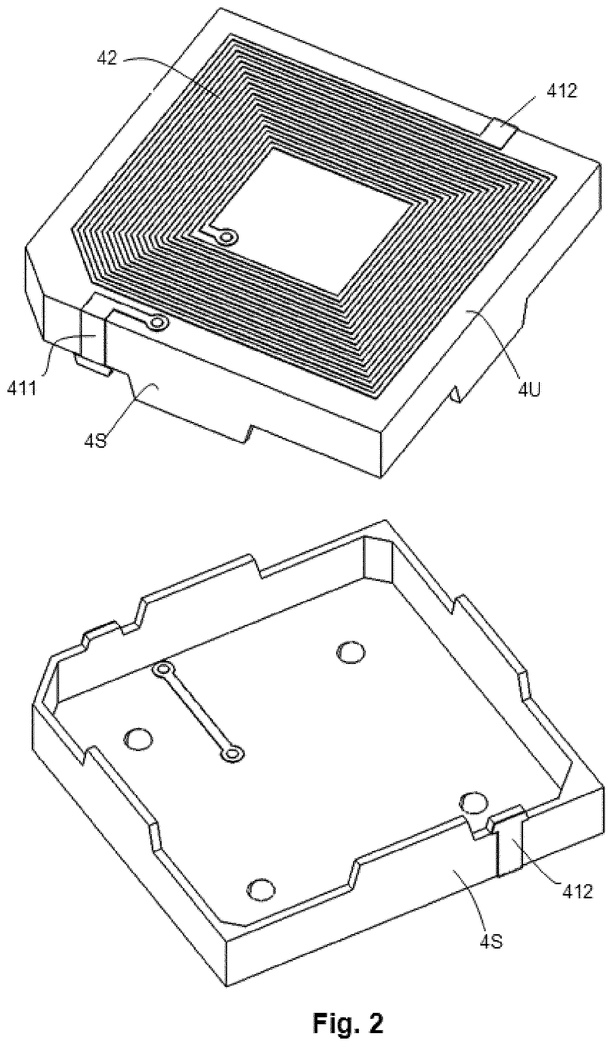
[0009]Unlike to the known antenna structure, the proposed antenna device further comprises an electrically insulated cap (for example a plastic cap) having an upper surface and a s...
PUM
 Abstract
Description
Claims
Application Information