Tunable high power waveguide band-stop filter

A band-stop filter and high-power technology, applied in the field of filters, can solve the problem of single frequency selection characteristics, etc., and achieve the effects of reducing interference, novel structure, and enhancing applicability

Active Publication Date: 2015-08-26
河南方达空间信息技术有限公司
View PDF4 Cites 7 Cited by
  • Summary
  • Abstract
  • Description
  • Claims
  • Application Information

AI Technical Summary

Problems solved by technology

[0002] With the development of wireless communication technology and the advancement of global informatization, a large number of radio signals need to be transmitted through radio frequency, microwave and other communication systems, and communication systems in different frequency bands can only work normally in their corresponding frequency bands, which requires The filter in the communication system has high accuracy in frequency selection, so as to achieve greater attenuation of noise signals such as unwanted interference, spurious and spurious, and to attenuate the required signal in the communication system with as little attenuation as possible. However, with the development of civilian communication systems and military communication systems, a large amount of information needs to be transmitted between communication systems with limited frequency band resources, which requires the communication system to have faster transmission speed, wider transmission bandwidth and Stronger anti-interference ability, which to some extent determines that the filter that has a direct impact on various performance indicators of the communication system must have better performance, especially in applications such as microwave deep space exploration, due to the microwave signal The frequency is high, the energy is large, and it has a wide frequency band. In the past, the filter with a small power capacity and a single frequency selection characteristic could not meet its actual needs.

Method used


Image

  • Tunable high power waveguide band-stop filter
  • Tunable high power waveguide band-stop filter
  • Tunable high power waveguide band-stop filter

Examples


Embodiment Construction

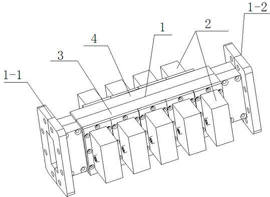
[0021] Such as figure 1 As shown, the present invention includes a main waveguide cavity 1 and at least two secondary waveguide cavities 2 with the same structure, and multiple secondary waveguide cavities 2 are respectively fixed on the front and rear sides of the main waveguide cavity 1 .

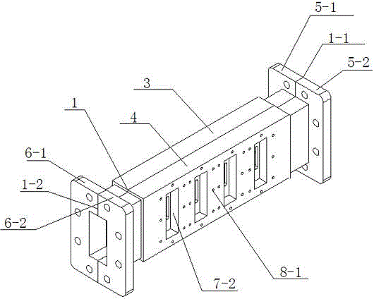
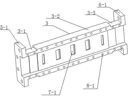
[0022] Such as Figure 2 to Figure 5 As shown, the main waveguide cavity 1 adopts a cavity structure with a left interface 1-1 and a right interface 1-2, including a first shell 3 and a second shell 4 fixed together, and both shells are It includes a left connecting part, a middle part and a right connecting part; the left ends of the left connecting part 3-1 of the first housing and the left connecting part 4-1 of the second housing are provided with the first left half waveguide interface 5-1 and the second half waveguide interface respectively. The left half waveguide interface 5-2, and the first left half waveguide interface 5-1 and the second left half waveguide interface 5-2 joint...


PUM


Abstract

The invention discloses a tunable high power waveguide band-stop filter comprising a main waveguide cavity with a left interface and a right interface, and at least two auxiliary waveguide cavities with same structures and respectively having one interface and a tuning structure; two opposite side faces of the main waveguide cavity are respectively provided with a rectangular coupling port, wherein the size of the rectangular coupling port is matched with an interface size of the auxiliary waveguide cavity; the auxiliary waveguide cavities are fixed on the rectangular coupling ports of the main waveguide cavity; the cavities of the main waveguide cavity and the auxiliary waveguide cavities are connected. The tunable high power waveguide band-stop filter is large in power capacity, strong in practicality, tunable in work frequency, and the whole filter is novel in structure, light in weight, and provides supports for micromation and integration of a subsequent system.

Description

technical field [0001] The invention relates to a filter applied in the fields of radio frequency and microwave, in particular to a tuneable high-power waveguide band-stop filter. Background technique [0002] With the development of wireless communication technology and the advancement of global informatization, a large number of radio signals need to be transmitted through radio frequency, microwave and other communication systems, and communication systems in different frequency bands can only work normally in their corresponding frequency bands, which requires The filter in the communication system has high accuracy in frequency selection, so as to achieve greater attenuation of noise signals such as unwanted interference, spurious and spurious, and to attenuate the required signal in the communication system with as little attenuation as possible. However, with the development of civilian communication systems and military communication systems, a large amount of inform...

Claims


Application Information

Patent Timeline
Patent Type & Authority Applications(China)
IPC IPC(8): H01P1/209
Inventor 刘海旭侯满红
Owner 河南方达空间信息技术有限公司
Why Eureka
Try Eureka