
Jig calibration method for selective compliance assembly robot arm (SCARA) robot

A calibration method and robot technology, applied in manipulators, manufacturing tools, claw arms, etc., can solve the problems of time-consuming, labor-intensive and cost-intensive, and achieve the effects of simple operation, low cost, data collection and simple construction

Active Publication Date: 2019-04-23
RIZHAO YUEJIANG TECH CO LTD
View PDF5 Cites 5 Cited by
  • Summary
  • Abstract
  • Description
  • Claims
  • Application Information

AI Technical Summary

Problems solved by technology

[0004] The purpose of the present invention is to provide a fixture calibration method for SCARA robots, aiming to solve the problems of time-consuming, laborious and high cost in the calibration of SCARA robots in the prior art

Method used


Image

  • Jig calibration method for selective compliance assembly robot arm (SCARA) robot
  • Jig calibration method for selective compliance assembly robot arm (SCARA) robot
  • Jig calibration method for selective compliance assembly robot arm (SCARA) robot

Examples


Embodiment Construction

[0016] In order to make the object, technical solution and advantages of the present invention clearer, the present invention will be further described in detail below in conjunction with the accompanying drawings and embodiments. It should be understood that the specific embodiments described here are only used to explain the present invention, not to limit the present invention.

[0017] The implementation of the present invention will be described in detail below in conjunction with specific embodiments.

[0018] In the drawings of this embodiment, the same or similar symbols correspond to the same or similar components; The indicated orientation or positional relationship is based on the orientation or positional relationship shown in the drawings, and is only for the convenience of describing the present invention and simplifying the description, rather than indicating or implying that the referred device or element must have a specific orientation, or in a specific orien...


PUM


Abstract

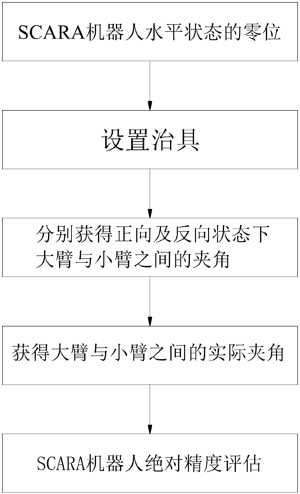
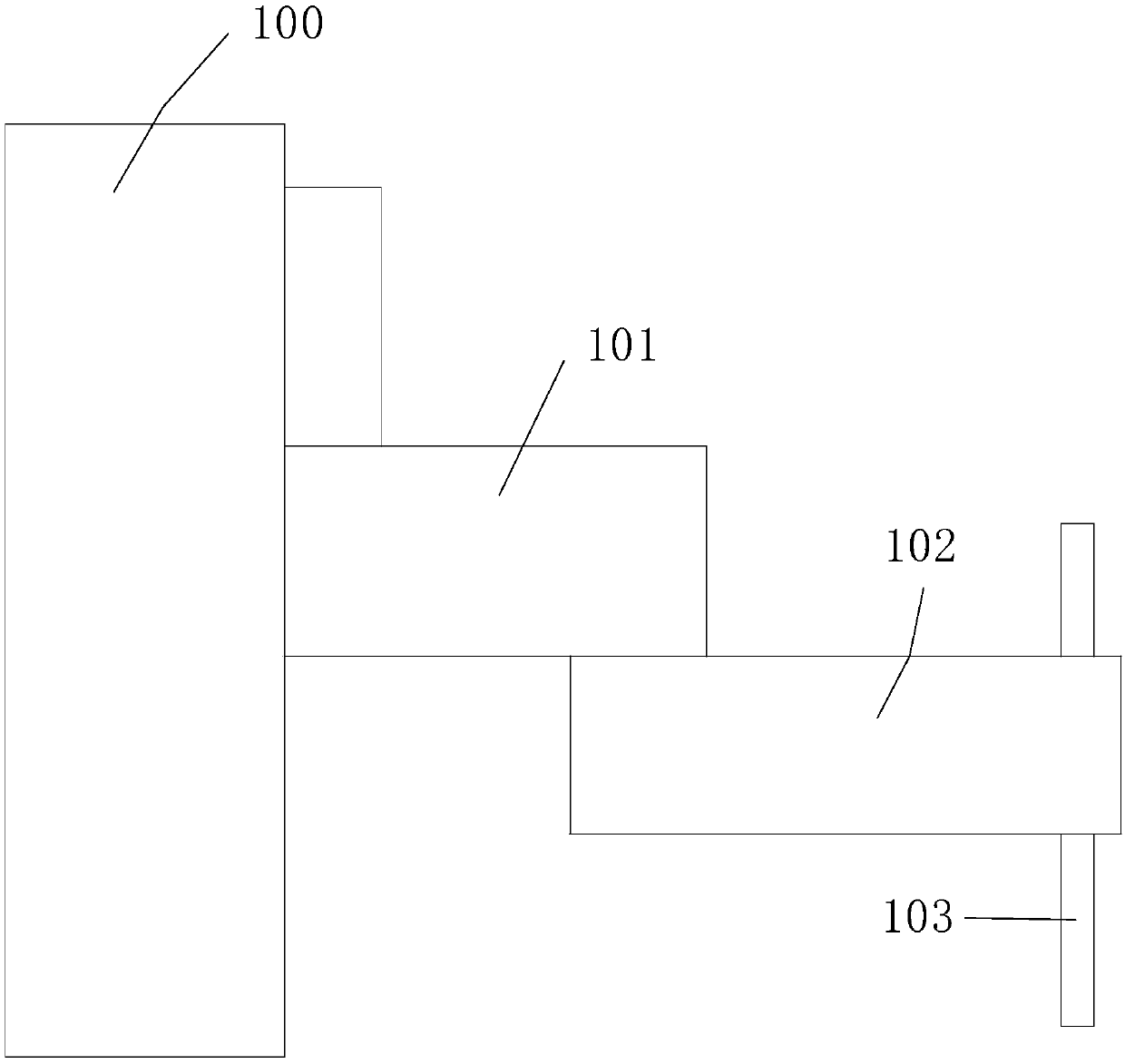
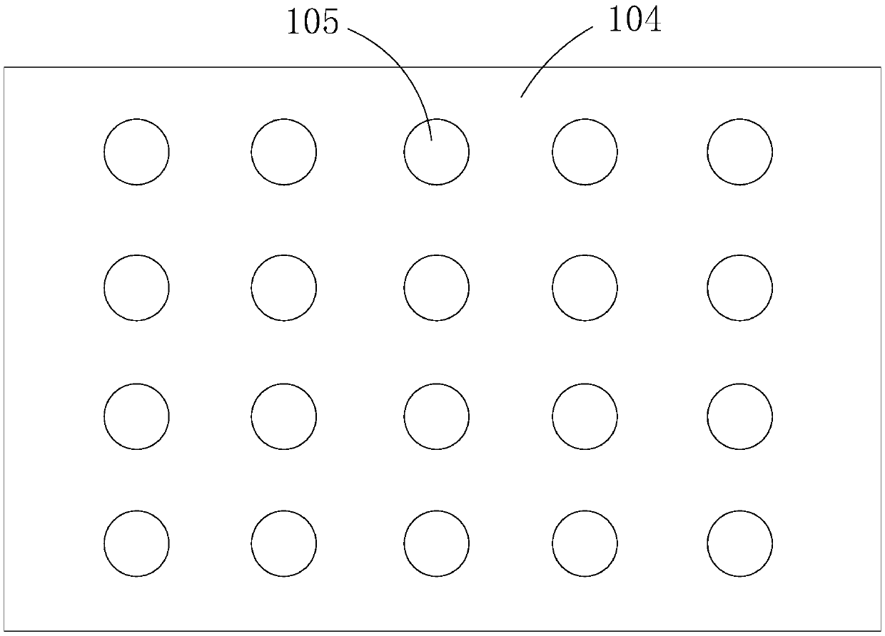
The invention relates to the technical field of selective compliance assembly robot arm (SCARA) robots, and discloses a jig calibration method for a selective compliance assembly robot arm (SCARA) robot. The jig calibration method for the SCARA robot comprises the following steps of (1) horizontally arranging a big arm and a small arm, and determining that the SCARA robot is located at a zero position at the horizontal state; (2) arranging a jig, vertically connecting a jig rod at the arm tail end of a mechanical arm, and forming a jig hole in the jig plate; (3) dragging the mechanical arm toswing in the forward direction until the jig rod at the tail end of the mechanical arm is inserted into the jig hole, wherein an included angle theta 1 is formed between the big arm and the small arm;and dragging the mechanical arm to swing in the reverse direction, wherein an included angle theta 2 is formed between the big arm and the small arm; and (4) according to the included angle theta 1 and the included angle theta 2, obtaining an actual included angle theta between the big arm and the small arm so as to calibrate the SCARA robot, wherein the actual theta is equal to (theta 1+theta 2) / 2. The jig calibration method for the SCARA robot is simple in operation, simple in data acquisition and establishment, saving in time and labor, and low in cost.

Description

technical field [0001] The patent of the present invention relates to the technical field of SCARA robots, specifically, to a fixture calibration method of SCARA robots. Background technique [0002] SCARA is the abbreviation of Selective Compliance Assembly Robot Arm, which means a robot arm applied to assembly operations. The SCARA robot has 3 rotary joints and is most suitable for plane positioning. [0003] At present, the calibration of SCARA robots mostly uses laser trackers or vision measuring instruments for calibration. These measuring instruments have great differences in accuracy, cost, time efficiency and ease of use. However, using these measuring instruments for calibration, However, there are common defects: professional and technical personnel are required to operate these measuring instruments. During the calibration process, platform construction and data collection are time-consuming and labor-intensive, and the cost is also high. Contents of the invent...

Claims


Application Information

Patent Timeline
Patent Type & Authority Applications(China)
IPC IPC(8): B25J17/02B25J18/00
CPCB25J17/02B25J18/00
Inventor 朗需林刘培超黄睿林炯辉曹林攀
Owner RIZHAO YUEJIANG TECH CO LTD
Learn More