Multifunctional self-timer stick

A selfie stick and multi-functional technology, applied in the field of selfie sticks, can solve the problems of low degree of freedom of selfie stick rotation, inflexible use, poor user experience, etc., achieve good structural fusion characteristics, facilitate long-distance shooting, and improve user experience Effect

Pending Publication Date: 2019-04-23
SHENZHEN LUXURY UNITED TECH CO LTD
View PDF12 Cites 8 Cited by
  • Summary
  • Abstract
  • Description
  • Claims
  • Application Information

AI Technical Summary

Problems solved by technology

[0003] With the diversification of shooting scenes, there are more and more requirements for the use of selfie sticks. It is no longer limited to handheld use. Sometimes it is necessary to place the selfie stick for use. At this time, the selfie stick needs to be independently installed; in addition , the size and volume of the existing brackets with supporting feet are large, and the supporting feet are fixed and stored on the outer surface of the seat body, resulting in complex and messy structures, cumbersome operations, and poor user experience
Moreover, with the diversification of shooting needs, sometimes it is necessary to use a mobile phone to take full-angle shots. When taking full-angle shots, the phone needs to be rotated. When using the existing selfie stick to control the mobile phone for panoramic shots, the shaking of the arm will reduce the shooting quality.
Moreover, with the diversification of shooting needs, sometimes it is necessary to use a mobile phone to take pictures from a lower position, and the long-term holding of the existing straight selfie stick is harmful to human health.
Moreover, the degree of freedom of rotation of the selfie stick in the prior art is low, and it is not flexible when used, and the user experience is poor.

Method used


Image

  • Multifunctional self-timer stick
  • Multifunctional self-timer stick
  • Multifunctional self-timer stick

Examples


Embodiment

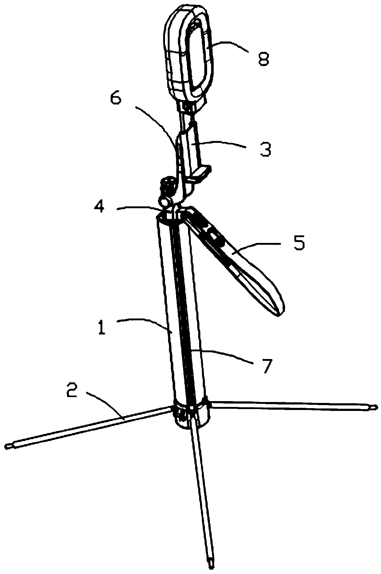
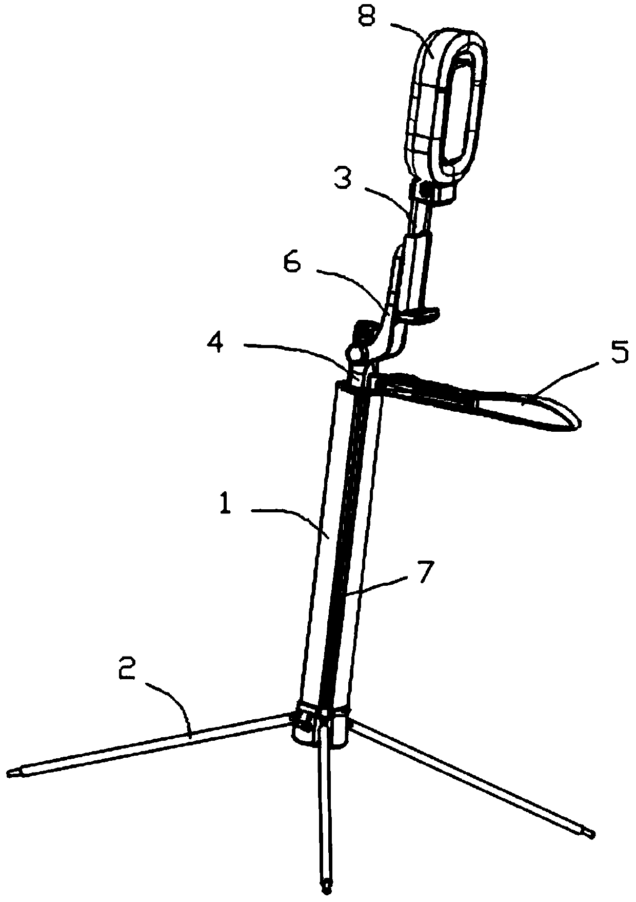
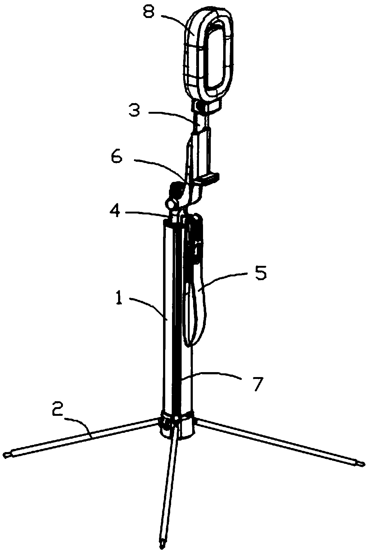
[0053] This embodiment provides a multifunctional selfie stick, including a bracket, a clamping device 3 and an auxiliary handle 5 . Wherein, the bracket is a supporting part of the multifunctional selfie stick, and is used for supporting the multifunctional selfie stick on the ground or a workbench as a whole. A connecting head 4 is rotatably connected to the top of the bracket, and the clamping device 3 is configured to clamp an electronic device 24, wherein the electronic device 24 includes a mobile phone, a tablet computer and the like. The clamping device 3 is movably connected to the joint 4, and the auxiliary handle 5 is hinged to the joint 4. There is a lock handle assembly between the joint 4 and the auxiliary handle 5. The lock handle assembly is used to make the auxiliary handle 5 relative to the joint 4 in a locked state. The holding position is fixed and the auxiliary handle 5 can be rotated relative to the connecting head 4 in the unlocked state. in, Figure 4 ...


PUM


Abstract

The invention provides a multifunctional self-timer stick, comprising a bracket, a clamping device, and an auxiliary handle, wherein the top of bracket is rotatianlly connected with a connecting head;the clamping device is configured to clamp electronic equipment; the clamping device is movably connected with the connecting head; the auxiliary handle is hinged with the connecting head; a lock handle assembly is arranged between the connecting head and the auxiliary handle; and the lock handle assembly is used for fixing the holding position of the auxiliary handle relative to the connecting head in a locking state and enabling the auxiliary handle to rotate relative to the connecting head in an unlocking state. On the basis of supporting by the bracket, the auxiliary handle can be used bya user to change the position of electronic equipment such as a mobile phone on the clamping device, so the stability during the position change process is improved obviously, especially the motion stability when the electronic equipment needs to be rotated during panoramic shooting is improved; the self-timer stick is beneficial to improving the shooting quality, more beneficial to ergonomic design, prevents the hand and arm of the user from being sore or diseased, and promots health and user experience.

Description

technical field [0001] The invention relates to the technical field of selfie sticks, in particular to a multifunctional selfie stick. Background technique [0002] With the increasing demand for mobile phone shooting, the selfie stick emerged as a shooting tool for holding the mobile phone. The selfie stick can be arbitrarily stretched within a certain length, and the user only needs to fix the mobile phone on the telescopic pole. , the selfie stick allows the user to have a longer shooting distance than the arm when shooting and can conveniently choose more shooting angles. [0003] With the diversification of shooting scenes, there are more and more requirements for the use of selfie sticks. It is no longer limited to handheld use. Sometimes it is necessary to place the selfie stick for use. At this time, the selfie stick needs to be independently installed; in addition , the size and volume of the existing brackets with supporting feet are relatively large, and the supp...

Claims


Application Information

Patent Timeline
Patent Type & Authority Applications(China)
IPC IPC(8): F16M13/04F16M11/38F16M11/04F16M11/10F16M11/18H04M1/04
CPCH04M1/04F16M11/04F16M11/10F16M11/18F16M11/38F16M13/04
Inventor 陈伟豪张恒菲
Owner SHENZHEN LUXURY UNITED TECH CO LTD
Why Eureka
Try Eureka