Electrical power supply switch for a protection module and protection module comprising such a switch

一种电源隔离、开关的技术,应用在保护开关的零部件、保护开关、保护开关操作/释放机构等方向

Active Publication Date: 2019-04-23
SCHNEIDER ELECTRIC IND SAS
View PDF8 Cites 2 Cited by
  • Summary
  • Abstract
  • Description
  • Claims
  • Application Information

AI Technical Summary

Problems solved by technology

Therefore, protective devices that cannot withstand the test voltage must be disconnected during the test

Method used


Image

  • Electrical power supply switch for a protection module and protection module comprising such a switch
  • Electrical power supply switch for a protection module and protection module comprising such a switch
  • Electrical power supply switch for a protection module and protection module comprising such a switch

Examples


Embodiment Construction

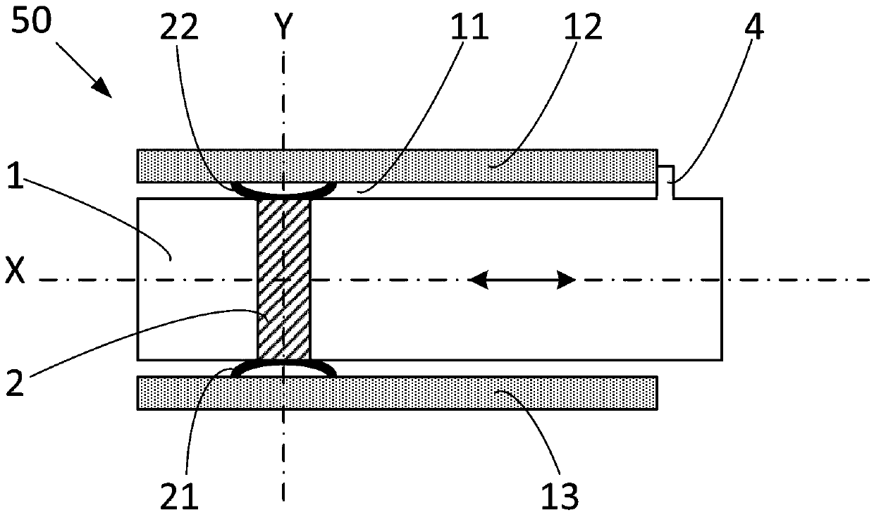
[0047] Mains isolating switches are most particularly used in electrical fault-protected modules to make or break a connection between a current conductor and a power circuit. This feature is important because it allows disconnection of the power circuit during dielectric testing. Figure 1A is a schematic diagram showing the mains disconnect switch 50 in a first position. The isolating switch is mainly composed of two parts: a housing 10 and a slider 1 . The housing 10 is preferably rectangular in cross-section and substantially parallelepiped-shaped, comprising a central channel 11 oriented along the central axis X. The housing is formed by a wall whose inner surface facing the central axis X defines a central channel 11 . The lower wall 13 has an inner surface facing the inner surface of the upper wall 12 . Two side walls (not in Figure 1A shown in ) facing each other. The other two sides are preferably open. The lower wall 13 carries on its inner surface at least one ...


PUM


Abstract

The invention relates to an electrical power supply switch for a protection module and a protection module comprising such a switch. The electrical power supply disconnector (50) is used for establishing or severing the connection between current conductors and a power supply circuit. The electrical power supply disconnector (50) includes a housing including a central passage (11), the walls (12,13) of which bear contact strips (21, 22, 23, 24) that are located facing one another along a contact axis (Y), and a slider (1) sliding through the central passage (11) in the direction of a centre axis (X), and bearing at least a first electrically conductive bar (2), oriented along the contact axis (Y), for electrically connecting at least one first low contact strip (21) and one high contact strip (22) when the slider (1) is in a first position.

Description

technical field [0001] The invention relates to a power isolating switch for use in a module for protection against electrical faults to establish or break the connection between a current conductor and the power circuit of said protection module. The invention also relates to a protection module comprising such a power isolating switch. Background technique [0002] Typically, electrical equipment includes one or more devices for protection against overcurrent or ground faults. Such devices are adapted to operate within a voltage range matching the nominal voltage of the grid to which they are connected, for example 400 volts AC. However, when testing the dielectric strength of electrical equipment, a test voltage much higher than the nominal voltage or of a different nature is applied to parts of the electrical equipment, such as 2500 volts AC or 500 volts DC. Therefore, protective devices that cannot withstand the test voltage must be disconnected during the test. In o...

Claims


Application Information

Patent Timeline
Patent Type & Authority Applications(China)
IPC IPC(8): H01H83/04
CPCH01H83/04H01H1/44H01H15/06H01H71/18H02H3/00H01H71/025H01H71/1045H01H2201/004H01H2203/024H01H2205/004H01H2205/028H01H2207/032H01H2229/018H01H2239/044H02H1/0007H02H3/083
Inventor F.布拉斯梅V.莫利顿B.勒费夫尔
Owner SCHNEIDER ELECTRIC IND SAS
Why Eureka
Try Eureka