
Eureka
For R&D, Eureka makes reading and utilizing patents & technical documents easy.
Eureka AIR
Designed for self-driven R&D workflows. Generate viable solutions, solve complex R&D challenges, empower your innovation with AI.

Eureka Materials
Designed for material experts only. Revolutionize your material R&D, from search, analyze, to developing new materials.

TechResearch
Generate reliable direction feasibility study reports for your R&D in just a few steps.

TechSeek
Discover and master advanced knowledge NOW. Basics, ideas, possibilities, all at once.

TechMind
As an expert in R&D Theories, TechMind can generates customized viable solutions instantly.

TechRisk
Analyze your overall solution with one click, know your potential R&D risks in advance.

TechMonitor
Get weekly tech updates, stay abreast of the latest tech innovations and key insights.
Intelligent center shaft, intelligent cube and timing method thereof
An intelligent and Rubik's Cube technology, applied in computing, sports accessories, instruments, etc., can solve the problems of high intelligence and low intelligence, and achieve the effect of high intelligence
- Summary
- Abstract
- Description
- Claims
- Application Information
AI Technical Summary
Problems solved by technology
Method used
Image

Examples
Embodiment 1
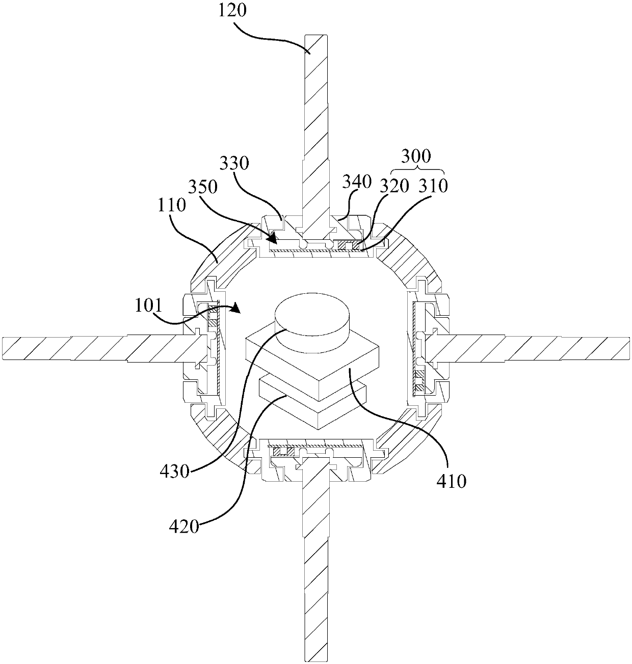
[0039] Such as figure 1As shown, an intelligent central axis includes a core, a sensor 300 and a main control module 410 . The core comprises a housing 110 having a cavity 101 . The sensor 300 is installed on the core, and the sensor 300 includes a stator 310 and a rotor 320 , and the stator 310 is fixed on the casing 110 . When the smart center axis is applied to the Rubik's Cube, the Rubik's Cube layer rotates relative to the housing 110, and the rotor 320 is configured to be connected to the Rubik's Cube layer and rotate synchronously, so that the rotor 320 can move with the Rubik's Cube layer relative to the stator. 310 turns. The main control module 410 is installed in the cavity 101 , the main control module 410 is electrically connected with the sensor 300 , and the main control module 410 obtains the rotation signal of the Rubik's cube layer according to the relative rotation between the rotor 320 and the stator 310 .
[0040] In the above-mentioned intelligent cent...
Embodiment 2
[0048] Embodiment 2 illustrates a specific scheme in which the rotor 320 realizes synchronous rotation with the Rubik's cube layer through the connecting rod 120 .
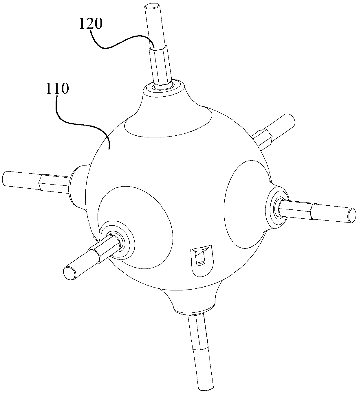
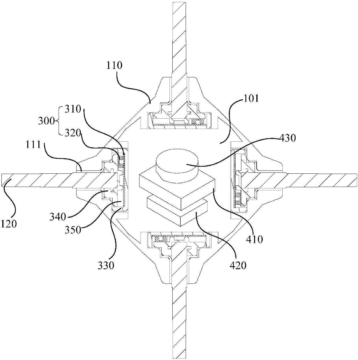
[0049] Such as figure 2 with image 3 As shown, the smart central axis also includes a connecting rod 120 . The rotor 320 is rotatably mounted on the casing 110 , and the connecting rod 120 is fixedly connected to the rotor 320 . Wherein, the connecting rod 120 is used to be fixedly installed with a central block or an intermediate connecting block, so that the connecting rod 120 can rotate synchronously with the rotation of the Rubik's cube layer. Layers rotate synchronously.
[0050] Specifically, combined with image 3 , the sensor 300 is located in the housing 110, the housing 110 is provided with a through hole, and the connecting rod 120 is connected with the rotor 320 after passing through the through hole. The sensor 300 is located in the casing 110 as a whole, which is beneficial to the protection o...
Embodiment 3
[0055] Embodiment 3 illustrates a specific scheme in which the rotor 320 is connected to the central block 210 or the intermediate connecting block 510 through the connection shell 360 to realize synchronous rotation with the Rubik's Cube layers.
[0056] The sensor 300 also includes a connection housing 360 . The connecting shell 360 is rotatably installed on the housing 110, and is used to connect with the central block 210 (see Figure 10 ) or intermediate connection block 510 (see Figure 4 to Figure 8 ) fixed connection. see Figure 10 , The bottom of the center block 210 is provided with a card slot 211 , and the connecting shell 360 is locked into the card slot to achieve a fixed connection with the center block 210 . The rotor 320 is fixed to the connection case 360 . Wherein, the central block 210 or the intermediate connecting block 510 will rotate synchronously with the Rubik's cube layer, so that the connection shell 360 and the rotor 320 realize synchronous ...
PUM
 Abstract
Description
Claims
Application Information
 - R&D Engineer
- R&D Manager
- IP Professional
- Industry Leading Data Capabilities
- Powerful AI technology
- Patent DNA Extraction
Browse by: Latest US Patents, China's latest patents, Technical Efficacy Thesaurus, Application Domain, Technology Topic, Popular Technical Reports.
© 2024 PatSnap. All rights reserved.Legal|Privacy policy|Modern Slavery Act Transparency Statement|Sitemap|About US| Contact US: help@patsnap.com