Charging system for unmanned aircraft

A technology of unmanned aircraft and charging system, applied in electromagnetic wave systems, electrical components, circuit devices, etc., can solve the problems that unmanned aircraft cannot fly in the air for a long time, the working radius of unmanned aircraft is small, and there are many manpower and material resources , to achieve the effect of expanding the flight working radius, solving the unstable charging voltage and improving the power quality

Active Publication Date: 2014-06-18
王洋 +3
View PDF3 Cites 54 Cited by
  • Summary
  • Abstract
  • Description
  • Claims
  • Application Information

AI Technical Summary

Problems solved by technology

[0004] Existing electric drones usually return to the ground base when they need to be charged, and then remove the battery to charge or replace the battery. The disadvantages of this method are: first, the flying radius of the unmanned aircraft is small
Since battery life is limited by battery capacity and performance, unmanned aircraft cannot fly in the air for a long time. When the battery is exhausted, it needs to return to the ground base; secondly, it requires a lot of manual work
Although increasing the distribution density of ground bases or ground mobile base stations can increase the working radius of unmanned aircraft, the establishment of multiple bases or mobile base stations requires more manpower and material resources, which greatly increases economic costs.

Method used


Image

  • Charging system for unmanned aircraft
  • Charging system for unmanned aircraft
  • Charging system for unmanned aircraft

Examples


Embodiment Construction

[0035] The present invention will be further described in detail below in conjunction with the accompanying drawings and embodiments.

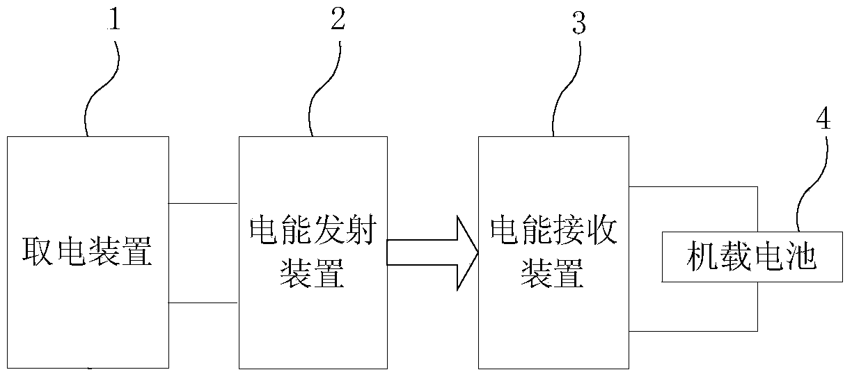
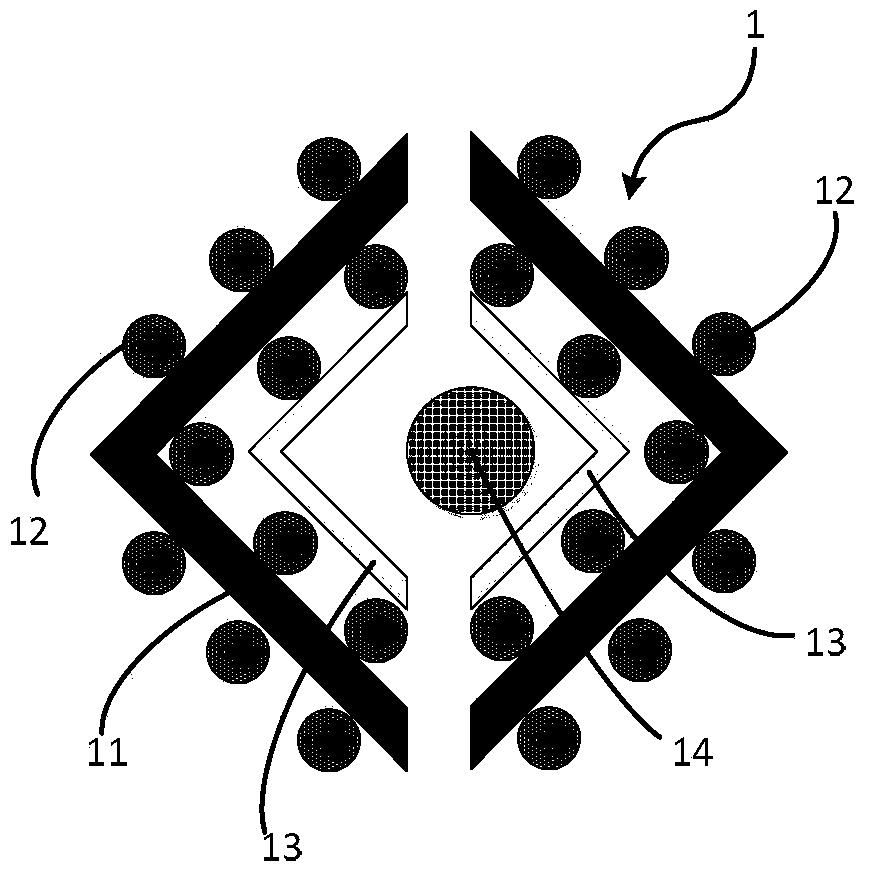
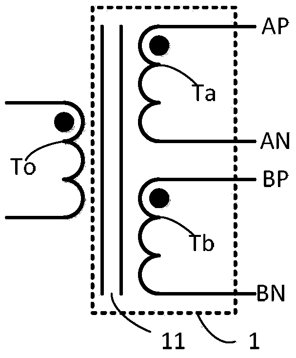
[0036] Such as Figure 1-13 As shown, the present embodiment relates to a charging system for an unmanned aircraft, the charging system includes a power taking device 1, a power transmitting device 2, a power receiving device 3 and an onboard battery 4; the power taking device 1 is installed on an overhead On the transmission line 14, the overhead transmission line 14 can be a twisted wire formed by a single-strand wire passing through the current or can be a twisted wire composed of non-insulated multi-strand wires passing through the current; an insulator is installed on the tower of the overhead transmission line 14, The power transmitting device 2 is arranged on the top of the insulator, and the power transmitting device 2 can be used to convert the power frequency alternating current into high frequency alternating current for wireless ch...


PUM


Abstract

The invention discloses a charging system for an unmanned aircraft. The charging system is characterized by comprising a power-taking device, an electric energy transmitting device, an electric energy receiving device and an aircraft-mounted battery, wherein an overhead transmission line is arranged on the power-taking device; the electric energy transmitting device is for converting power frequency alternating current into high-frequency alternating current; the electric energy receiving device is arranged on the unmanned aircraft; electric energy transmission is realized in a wireless manner between the electric energy receiving device and the electric energy transmitting device; the aircraft-mounted battery is arranged on the unmanned aircraft, is used for supplying power to the unmanned aircraft, and is connected in series to a current loop of the electric energy receiving device. Compared with the prior art, an electric unmanned aircraft charging system based on an alternating-current power transmission overhead line provided by the invention has the advantages that a full-autonomous and safe charging way is realized for the unmanned aircraft, and the distance per charge of the unmanned aircraft is prolonged. Meanwhile, a high-frequency inductive constant-current charging circuit based on an unstable alternating-current power supply is provided, so that unmanned charging operation is fully realized, the dependence of the unmanned aircraft on a ground base or a mobile base station is reduced, labor operation is reduced, and labor cost is reduced.

Description

technical field [0001] The invention relates to a charging system, in particular to a charging system for unmanned aircraft. Background technique [0002] With the development of the times, society's demand for aerial missions is becoming stronger and stronger. Compared with manned aircraft, drones have many incomparable advantages: relatively small size, flexible overall layout, low cost, easy to use, can enter dangerous environments, and can meet the needs of special purposes. [0003] An electric drone is an aircraft powered by an electric motor rather than an internal combustion engine, and sources of power include fuel cells, solar cells, supercapacitors, wireless energy transfer, or other types of batteries. Electric aircraft uses electric propulsion system instead of internal combustion engine power, which has gained many advantages and unique qualities. The most prominent advantages are energy saving and environmental protection, high efficiency and low energy consu...

Claims


Application Information

Patent Timeline
Patent Type & Authority Applications(China)
IPC IPC(8): H02J17/00H02M5/458H02J50/10
Inventor 王洋李大鹏蒋栋张硕
Owner 王洋
Why Eureka
Try Eureka