Side-suction pipe liquid mixing and conveying valve-less piezoelectric pump

A valveless piezoelectric pump and liquid mixing technology, which can be used in liquid variable capacity machinery, liquid fuel engines, components of pumping devices for elastic fluids, etc., and can solve problems such as low efficiency

Inactive Publication Date: 2016-06-15
BEIJING UNION UNIVERSITY
View PDF7 Cites 2 Cited by
  • Summary
  • Abstract
  • Description
  • Claims
  • Application Information

AI Technical Summary

Problems solved by technology

The two liquids to be transported always flow out of the liquid source, which overcomes the defect of low efficienc

Method used


Image

  • Side-suction pipe liquid mixing and conveying valve-less piezoelectric pump
  • Side-suction pipe liquid mixing and conveying valve-less piezoelectric pump
  • Side-suction pipe liquid mixing and conveying valve-less piezoelectric pump

Examples


Embodiment Construction

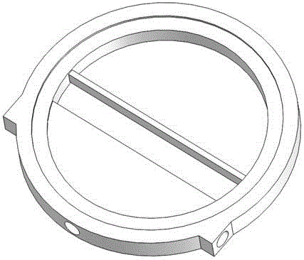
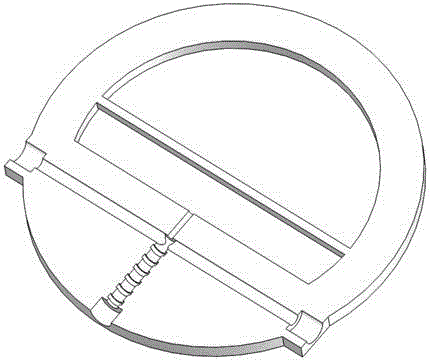
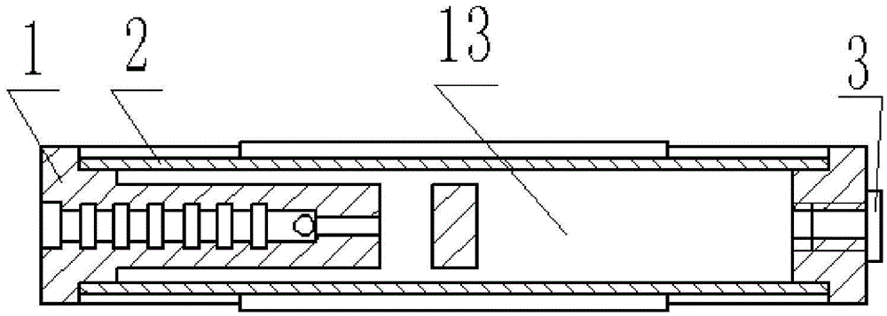
[0019] The embodiment of the present invention is as figure 1 - Figure 5 shown

[0020] Two identical piezoelectric vibrators 2 are installed face to face on the upper and lower sides of the pump body 1 with the same polarity side of the piezoelectric ceramics. The structure of the pump body 1 is as follows: figure 2 , image 3 , Figure 4 and Figure 5 As shown, there are counterbores 6 on the upper and lower end surfaces 12 of the pump body 1, and the piezoelectric vibrator 2 is installed in the counterbore 6, and the two piezoelectric vibrators 2 and the space in the pump body 1 form a pump chamber 13, and the pump chamber 13 is A cylindrical shape, the pump chamber 13 has a support plate 4 on the middle surface symmetrical to the upper and lower piezoelectric vibrators 2, the support plate 4 is located in the middle of the pump chamber 13, and the area occupied by the support plate 4 is less than half of the cross-sectional area of ​​the pump chamber 13. There is a ...


PUM


Abstract

The invention discloses a side-suction pipe liquid mixing and conveying valve-less piezoelectric pump, and belongs to the field of liquid machines. Two identical piezoelectric vibrators are mounted on the upper side and the lower side of a pump body face to face, the upper end face and the lower end face of the pump body are each provided with a counter bore, and the piezoelectric vibrators are mounted in the counter bores. A pump cavity is formed by the two piezoelectric vibrators and a space in the pump body and is cylindrical. A supporting plate is arranged on a middle surface of the pump cavity, and the upper piezoelectric vibrator and the lower piezoelectric vibrator are symmetrical with respect to the middle surface. The supporting plate is located in the middle of the pump cavity, a step is arranged between the supporting plate and the bottom face of one counter bore, the thickness of the supporting plate is made to be smaller than the height of the pump cavity, and the thickness of a cross beam is smaller than the height of the pump cavity. A circular main outer pipe and a circular main inner pipe are arranged in the middle of the end face perpendicular to the supporting plate, and a first branch pipe and a second branch pipe are further arranged in the supporting plate. By means of the side-suction pipe liquid mixing and conveying valve-less piezoelectric pump, two kinds of liquid are conveyed while being mixed through the piezoelectric pump, and the two kinds of liquid flow out of a liquid source all the time, so that the defect of low efficiency caused by repeated flowing of the liquid in a flow channel while an existing valve-less piezoelectric pump works is overcome.

Description

technical field [0001] The invention relates to a valveless piezoelectric liquid mixing pump, which belongs to the field of liquid machinery. Background technique [0002] The valveless piezoelectric pump has simple structure, high electromechanical energy conversion efficiency and high reliability, and has broad application prospects in the fields of medical care, aerospace, micro-electromechanical and other fields in the future. The structure proposed in the present invention can combine the two functions of liquid mixing and transportation, so that the two liquids can be mixed while being input, and the two liquids overcome this shortcoming, so that the valveless piezoelectric pump can work , and during the mixed delivery process, the liquid always keeps flowing into the pump body without backflow, so it can be used in occasions where the liquid source does not allow reverse flow. Contents of the invention [0003] The purpose of the present invention is to make the pi...

Claims


Application Information

Patent Timeline
IPC IPC(8): F04B43/04F04B53/00
CPCF04B43/0027F04B43/046F04B53/00
Inventor 夏齐霄卢振洋季红益
Owner BEIJING UNION UNIVERSITY
Why Eureka
Try Eureka