Signal remote transmission gas relay

A relay and gas technology, applied in the direction of circuits, electric switches, electrical components, etc., can solve the problem that the oil level of gas relays can only be monitored manually on site, and achieve the effect of improving the efficiency of oil level monitoring and perfecting the protection structure

Pending Publication Date: 2021-03-02
XIAN YA NENG ELECTRIC CO LTD
View PDF0 Cites 2 Cited by
  • Summary
  • Abstract
  • Description
  • Claims
  • Application Information

AI Technical Summary

Problems solved by technology

[0004] The present invention aims at the technical defects of the prior art, and provides a signal remote transmission gas relay to solve the technical problem that the oil level of conventional gas relays can only be monitored manually on site

Method used


Image

  • Signal remote transmission gas relay
  • Signal remote transmission gas relay
  • Signal remote transmission gas relay

Examples


Embodiment 1

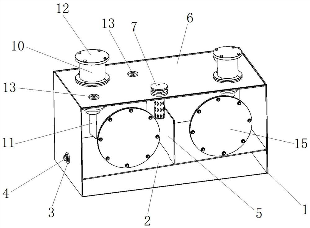
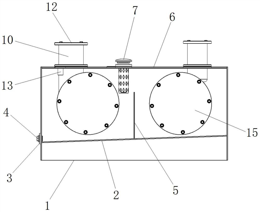
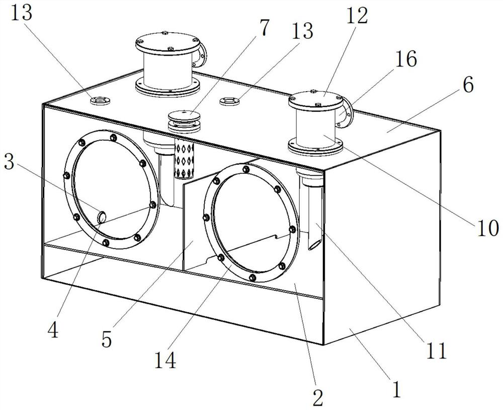
[0024]A signal remote transmission Buchholz relay, such asFigure 1~4As shown, it includes the housing 1, the inclined plate 2, the communication port 3, the plug 4, the central partition 5, the top surface 6, the air release valve 7, the cylinder 8, the diamond hole 9, the sleeve 10, the communication pipe 11, The flange cover 12, the camera 13, the front port 14, the front cover 15, and the bypass pipe 16, wherein a tilting plate 2 is fixedly connected to the inside of the housing 1, and is located at the end of the tilting plate 2 on the side wall of the housing 1 A communication port 3 is opened at the position of the communication port 3, and a plug 4 is provided at the communication port 3. A central partition 5 is vertically and fixedly connected to the inner wall of the housing 1. The central partition 5 is located above the inclined plate 2; An air release valve 7 is fixedly connected to the top surface 6 of the housing 1, and a cylinder 8 is provided at the lower end of the...

Embodiment 2

[0027]A signal remote transmission Buchholz relay, such asFigure 1~4As shown, it includes the housing 1, the inclined plate 2, the communication port 3, the plug 4, the central partition 5, the top surface 6, the air release valve 7, the cylinder 8, the diamond hole 9, the sleeve 10, the communication pipe 11, The flange cover 12, the camera 13, the front port 14, the front cover 15, and the bypass pipe 16, wherein a tilting plate 2 is fixedly connected to the inside of the housing 1, and is located at the end of the tilting plate 2 on the side wall of the housing 1 A communication port 3 is opened at the position of the communication port 3, and a plug 4 is provided at the communication port 3. A central partition 5 is vertically and fixedly connected to the inner wall of the housing 1. The central partition 5 is located above the inclined plate 2; An air release valve 7 is fixedly connected to the top surface 6 of the housing 1, and a cylinder 8 is provided at the lower end of the...


PUM


Abstract

The invention provides a signal remote transmission gas relay. According to the technical scheme, the external structure of the gas relay is improved, and meanwhile, the image acquisition module is introduced. Specifically, the bottom face of the containing cavity is designed to be the inclined face so that one-way movement of oil can be guaranteed, and meanwhile the middle partition plate is additionally arranged so that large fluctuation can be avoided in the oil flowing process. On the basis, the camera is additionally arranged at the top of the device, a liquid level image can be transmitted to a background in real time and remotely monitored by a worker, and frequent on-site checking actions are omitted. In addition, the sleeve is used for protecting the binding post, and a circuit can enter and exit from the side end; and during maintenance, the flange cover at the upper end can be opened, so that the installation and maintenance of the equipment are not influenced. According tothe invention, the oil level monitoring efficiency of the gas relay is improved, and a more perfect protection structure is provided.

Description

Technical field[0001]The invention relates to the technical field of Buchholz relays, in particular to a signal remote transmission Buchholz relay.Background technique[0002]Buchholz relay, also known as gas relay, is a protection device used in transformers. It is installed in the pipeline between the oil conservator and the oil tank of the transformer. The internal fault of the transformer causes the oil to decompose and generate gas or cause the oil flow to surge. The contact action of the gas relay connects to the designated control circuit, and promptly sends out a signal alarm (light gas) or activates the protective element to automatically cut off the transformer (heavy gas).[0003]The light gas mainly reflects that the gas decomposed by the oil rises into the gas relay during operation or minor faults. The air pressure causes the oil level to drop. The open cup of the relay drops with the oil surface, and the light gas reed contact is connected to send a signal. When there is ...

Claims


Application Information

Patent Timeline
Patent Type & Authority Applications(China)
IPC IPC(8): H01H33/55H01H33/02H01H9/02H01F27/40
CPCH01F27/402H01F2027/404H01H9/02H01H9/0271H01H33/02H01H33/025H01H33/555
Inventor 王习明
Owner XIAN YA NENG ELECTRIC CO LTD
Why Eureka
Try Eureka