
Heavy oil viscosity reduction device

A technology for reducing viscosity and heavy oil, which is applied in the pipeline system, gas/liquid distribution and storage, mechanical equipment, etc. It can solve the problems of unsmooth transportation operations, lower oil transportation efficiency, and easy blockage of oil pipelines, etc., to achieve Simple structure, reduced viscosity, and improved transportation efficiency

Inactive Publication Date: 2015-11-18
浙江泰嘉光电科技有限公司
View PDF4 Cites 17 Cited by
  • Summary
  • Abstract
  • Description
  • Claims
  • Application Information

AI Technical Summary

Problems solved by technology

[0002] In the process of oil extraction, due to the high viscosity of heavy oil, the transportation of heavy oil is greatly affected, making it stick to the inner wall of the oil pipeline, reducing the efficiency of oil transportation, and it is easy to block the oil pipeline, making the transportation operation impossible. go on smoothly

Method used


Image

  • Heavy oil viscosity reduction device

Examples


Embodiment Construction

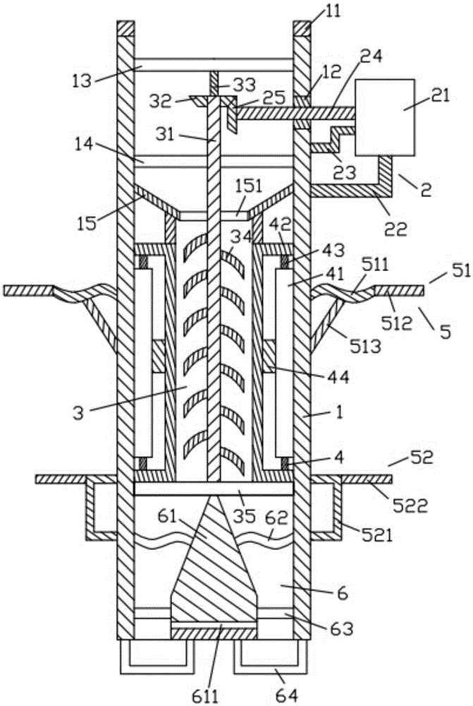
[0019] Such as figure 1 As shown, the heavy oil viscosity reducing device of the present invention includes a frame body 1, a rotating device 2 arranged on the frame body 1, a stirring device 3 inside the frame body 1, and a heating device around the heating device 3. 4. The holding device 5 arranged on the frame body 1 and the oil separating device 6 located below the stirring device 3 .

[0020] Such as figure 1 As shown, the frame body 1 is a hollow cylinder, and the frame body 1 is placed vertically. The frame body 1 is provided with a first sealing ring 21, a first sealing ring 12 located on the right surface, and a first sealing ring 12 located inside. The first filter 13 , the second filter 14 below the first filter 13 , the collecting hopper 15 below the second filter 15 and the support ring below the collecting hopper 15 . The first sealing ring 21 is circular, the first sealing ring 21 is placed horizontally, and the lower surface of the first sealing ring 21 is fi...


PUM


Abstract

A heavy oil viscosity reduction device comprises a frame, a rotary device, a stirring device, a heating device, holding devices and an oil distributing device. The frame is provided with a first sealing ring, a first sealing washer, a first filter screen, a second filter screen, a collecting hopper and a supporting ring. The rotary device comprises a motor, a first support, a first rotary shaft, a first fixing rod and a first gear. The stirring device comprises a first supporting rod, a second rotary shaft, a second gear, a stirring rod and a third filter screen. The heating device comprises a heating bar, a heat conductive frame, a first fixing block and a second fixing block. The holding devices include the first holding device and the second holding device. The first holding device comprises a first bent rod, a first transverse rod and an inclined rod. The second holding device comprises a second transverse rod and a second support. The oil distributing device comprises an oil distributing block, a fourth filter screen, a fifth filter screen and a filter frame. The oil distributing block is provided with a second through hole. By means of the heavy oil viscosity reduction device, heavy oil is heated and stirred so that the viscosity of the heavy oil can be greatly reduced.

Description

technical field [0001] The invention relates to the technical field of petroleum, in particular to a heavy oil viscosity reducing device. Background technique [0002] In the process of oil extraction, due to the high viscosity of heavy oil, the transportation of heavy oil is greatly affected, making it stick to the inner wall of the oil pipeline, reducing the efficiency of oil transportation, and it is easy to block the oil pipeline, making the transportation operation impossible. Go on smoothly. [0003] Therefore, it is necessary to provide a new technical solution to solve the above technical problems. Contents of the invention [0004] The object of the present invention is to provide a heavy oil viscosity reducing device that can effectively solve the above technical problems. [0005] In order to solve the above technical problems, the present invention adopts the following technical solutions: [0006] A thick oil viscosity reducing device, the heavy oil viscosi...

Claims


Application Information

Patent Timeline
Patent Type & Authority Applications(China)
IPC IPC(8): F17D1/18
Inventor 赵媛媛
Owner 浙江泰嘉光电科技有限公司
Learn More